Commissioning
The installation steps up to operation are:
Step 1: Removing the transport lock
Short-circuit hazard when the machine is too cold
If the machine is transported from a cold environment into a warmer environment, a short circuit may occur caused by condensate.
- Before switching on the machine after transportation, ensure the following:
- The ambient air has the allowed temperature.
- The machine has the same temperature as the ambient air. This will take at least 48 hours.
- The machine is completely dry.
Before operating the machine for the first time, you must remove the transport lock in the machine working chamber. The transport lock prevents the spindle from getting damaged during transport.
- Ensure the following:
- The machine is connected to the electrical source.
- The CAM computer
 The computer that is connected to your machine and which runs DentalCAM and DentalCNC. is not connected to the machine.
 - Switch on the machine at the main power switch.
- Open the working chamber door.
- Switch off the machine at the main power switch.
- Remove the transport lock as shown in the supplement.
Step 2: Integrating the machine into the network
The following diagram visualizes how commands are sent to the machine with our network technology:

SX Virtual Link is similar to a device driver that transfers data between DentalCNC and the machine.
The network integration workflow is as follows:
- Preparing the installation
- Configure SX Virtual Link and DentalCNC.
Preparing the installation
For integrating the machine into your network, you will require the assistance of your IT specialist.
-
Ensure that your network is working without disruptions. Network failures will lead to aborted jobs and unusable machining results.
-
Do not contact customer support for setting up your network or troubleshooting network issues. Customer service will only help you with machine-related issues.
- If you want to control multiple machines with 1 CAM computer The computer that is connected to your machine and which runs DentalCAM and DentalCNC., use our multi-machine control feature. See the documentation for the manufacturing software.
- Plug the Ethernet cable into the network port at the connection panel of the machine.
- Plug the other end of the Ethernet cable into the network port of the CAM computer The computer that is connected to your machine and which runs DentalCAM and DentalCNC.. Do not use a router, hub or switch to connect the 2 units at this point.
- Make sure that you have administrator rights on the CAM computer The computer that is connected to your machine and which runs DentalCAM and DentalCNC..
-
Install DentalCAM & DentalCNC. Installing DentalCAM & DentalCNC
-
During installation, the SX Virtual Link setup program
A separate program called "Setup.exe" which installs the applications on your hard drive. opens.
-
If the SX Virtual Link setup program
A separate program called "Setup.exe" which installs the applications on your hard drive. opened, continue with the next step.If the SX Virtual Link setup program
A separate program called "Setup.exe" which installs the applications on your hard drive. did not open, open the installation program in the DentalCAM & DentalCNC installation folder The folder on your hard drive that you installed DentalCAM and DentalCNC in..USB\Silex\Cosetup.exe
-
Follow the SX Virtual Link setup program
A separate program called "Setup.exe" which installs the applications on your hard drive. until the installation is finished. -
Continue with the DentalCAM & DentalCNC installation.

Configuring SX Virtual Link & DentalCNC
Watch the video

YouTube video – When viewing this video, personal data is sent to YouTube, LLC, USA. Privacy statement
-
Ensure that the CAM computer
The computer that is connected to your machine and which runs DentalCAM and DentalCNC. is directly connected to the machine via an Ethernet cable. Otherwise, the machine may obtain incorrect network settings and may become unreachable.If this happens, an on-site visit by customer service may be necessary: What to do if the machine is unreachable
- Switch on the machine at the main power switch.
-
The working chamber is illuminated in white.
The machine does not reference.
- Open the SX Virtual Link application window:
-
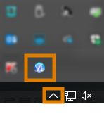
The software should already be running – select the arrow on the right side of your task bar to open the system tray.
In the system tray, select the SX Virtual Link icon.
- If the SX Virtual Link icon is not in the system tray, start the application via the start menu. You should find it in the Silex Device Server group.
-
The SX Virtual Link application window displays.
-
If SX Virtual Link cannot find your machine, the following image displays in the window:

-
If SX Virtual Link has found your machine, the internal network devices of the machine display in the window.
-
If the machine was found, continue with the next step.
If the machine was not found, do the following:
-
Check if the CAM computer
The computer that is connected to your machine and which runs DentalCAM and DentalCNC. is properly connected to the machine. -
Restart the machine.
-
 In the SX Virtual Link application window, select the depicted icon.
-
A more detailed list of the network devices displays.
- The internal devices of the machine
- The superior list entry for the machine
- In the SX Virtual Link window, right-click on SMI USB 2.0 Camera.
- From the context menu, select Properties….
- Switch to the Disconnect tab.
- Activate the Allow auto-disconnect when a Request Use is received check box.
- From the Auto-disconnect timeout drop-down list, select 10.
- To save your settings, select OK.
- Right-click on SMI PC Cam.
- From the context menu, select Connect.
- In the SX Virtual Link window, locate the device whose name starts with FTDI. Repeat steps 7 – 13 for this device.
- Green check marks (marked orange) indicate that the connections have been established.
 In the SX Virtual Link application window, select the depicted icon.
- The Options window opens.
- In the Options window, activate the following options:
- Launch SX Virtual Link at Windows startup
- Don't show SX Virtual Link main window on program launch
- Hide the main window if the close button is clicked
-
Deactivate the Automatically connect newly discovered USB devices option.
- To save your settings, select OK.
-
Start DentalCNC.
-
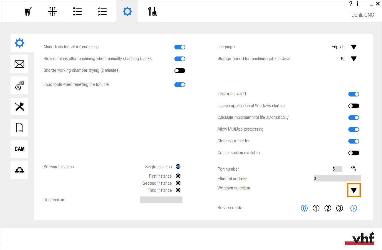
Open the DentalCNC Application settings with the following icon in the main icon bar:

-
Open the General settings with the following icon in the local icon bar:

-
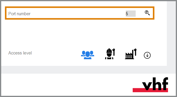
Select the following icon next to the Port number input field:

-
If DentalCNC is able to determine the port number, the number displays in the Port number input field. The machine references.
-
Read out the Ethernet address (marked orange) in the application window of SX Virtual Link. It displays behind the device name.

- Enter the Ethernet address into the Machine Ethernet address input field in DentalCNC.
Example:84:25:3F:23:4A:F4
- Press Enter.
- From now on, DentalCNC will connect and disconnect the machine.
- Activate the option Launch application at Windows startup in DentalCNC.
- From now on, DentalCNC will launch with Windows®. This is required to automate the connection process.
-
Quit DentalCNC.
If you do not close DentalCNC now, your changes may not be saved.
- In the SX Virtual Link application window, right-click on SMI USB 2.0 Camera.
- From the context menu, select Disconnect.
- Right click on the entry starting with FTDI.
- From the context menu, select Disconnect.
- In the SX Virtual Link application window, the 2 check marks no longer display.
- Start DentalCNC.
- DentalCNC establishes the connection to the machine. The 2 check marks display again.
-
(Optional) Install hub, router or switch to connect the computer and the machine. This may require additional configuration.


Step 3: Configuring the webcam
In the following cases, you need to configure the webcam of the machine:
- First installation of the machine
- Exchange of the CAM computer The computer that is connected to your machine and which runs DentalCAM and DentalCNC.
- Exchange of the control unit
- Exchange of the webcam
- Open the DentalCNC Application settings with the following icon in the main icon bar:
-
Open the General settings with the following icon in the local icon bar:
-
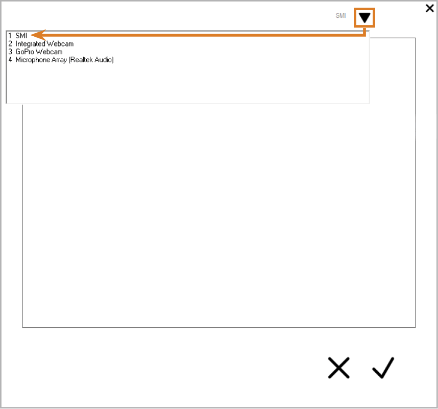
Select the following icon next to the Webcam selection label:

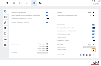
- Select the webcam SMI from the drop-down list at the top of the window.
-
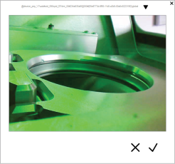
The current still image of the webcam displays.
- Select the depicted icon:

- The window closes. The webcam configuration is saved to the CAM computer The computer that is connected to your machine and which runs DentalCAM and DentalCNC..

Step 4: CAD/CAM integration
If you use exocad ChairsideCAD as your CAD application, you can activate the CAD/CAM integration with DentalCAM & DentalCNC 8.
If you use CAD/CAM integration, you will design and nest objects completely in the CAD application. When exporting, DentalCAM automatically calculates the machining strategy in the background and sends it to DentalCNC.
Minimum required exocad ChairsideCAD version:
|
3.0 (middle block position can be used) 3.2 (all block positions can be used) |
Activating the CAD/CAM integration
There are 2 ways to set up CAD/CAM integration with exocad ChairsideCAD:
-
exocad ChairsideCAD is installed on the CAM computer
The computer that is connected to your machine and which runs DentalCAM and DentalCNC.. This is recommended as it will simplify the configuration process.If you use this configuration, only perform the basic configuration.
-
exocad ChairsideCAD is installed on a separate computer (“CAD computer”), which is connected to the CAM computer
The computer that is connected to your machine and which runs DentalCAM and DentalCNC. via network.If you use this configuration, perform the basic configuration and the exocad network configuration.
Basic configuration
-
Open the DentalCNC Application settings with the following icon in the main icon bar:
-
Open the General settings with the following icon in the local icon bar:
-
Activate the CAD/CAM integration and 3Shape Produce enabled option.
-
If you have installed exocad ChairsideCAD on your CAM computer
The computer that is connected to your machine and which runs DentalCAM and DentalCNC., you are done. -
If exocad ChairsideCAD is installed on a separate CAD computer, continue with the exocad network configuration.

exocad network configuration
Only perform the following procedure if exocad ChairsideCAD is installed on a different computer than DentalCAM & DentalCNC.
Configuring the CAM computer
-
Access the CAM computer
The computer that is connected to your machine and which runs DentalCAM and DentalCNC.. -
Create the following folder:
C:\CADshare\DentalNestingObjToMDW
-
Share this folder in your network. The CAD computer requires read and write access to it.
Checking the data transfer folder setting
-
Open the DentalCNC Application settings with the following icon in the main icon bar:
-
Open the General settings with the following icon in the local icon bar:
-
Check if the following folder path displays under the CAD/CAM integration: Data transfer folder label:
 To store the data transfer folder in DentalCNC, select the depicted icon to the right of the CAD/CAM integration: Data transfer folder label.
-
A window for selecting the folder opens.
- From the drop-down list, select the drive letter c:.
- Select the following folder:
CADshare\DentalNestingObjToMDW
- Select the depicted icon.
- The selected folder displays below the CAD/CAM integration: Data transfer folder label.
C:\CADshare\DentalNestingObjToMDW
![]()
If it doesn’t, do the following:
Configuring the CAD computer
-
Access the CAD computer.
-
Install exocad ChairsideCAD.
-
Map a network drive to the C:\CADshare\DentalNestingObjToMDW folder that you created on the CAM computer.
-
Record the drive letter.
-
Enter the exact folder path including the leading backslashes \\.
-
Enter the login credentials for your CAM computer.
Store these login credentials on the CAD computer.
-
Activate the Reconnect at sign-in option.
-
Setting up exocad ChairsideCAD
-
In Windows® Explorer, open the exocad ChairsideCAD folder.
-
Change into the config folder.
-
Open the following file with a text editor:
-
Inside the file, find the following expression (“tag”):
-
Replace the output path with the letter of the network drive that you recorded followed by a colon (:).
-
Save and close the XML file.
settings-chairside.xml
<NestingInterop2TemporaryFolder>
Directly behind the expression, you will find the exocad output path.
Example: You recorded the drive letter Z. The expression in the XML file must be:
<NestingInterop2TemporaryFolder>Z:</NestingInterop2TemporaryFolder>
Step 5: Filling the cooling liquid
What's next?
If you want to create a job in DentalCAM:
If you want to process a job: