Milling test specimens and checking the values
Workflow Calibrating the machine.
Prerequisites
-
You have prepared the calibration.
-
You have prepared the micrometer.
-
You know how to execute a single job.
-
Open machine management with the following icon in the Main icon bar:

-
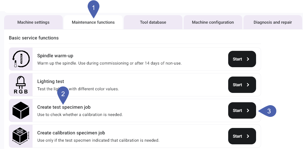
Select the Service functions tab.
-
In the Create test specimen job function, select the Start button.
-
dentalcnc adds the job to the queue.
-
Open the Manufacturing view with the following icon in the Main icon bar:

-
Manufacture the job like any other job.
-
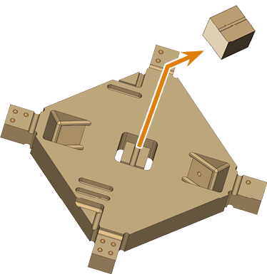
Remove the test specimen from the machine.
- E3
- E4
- E5
- K5, K5+, S5, S5m
- N4+
- R5
-
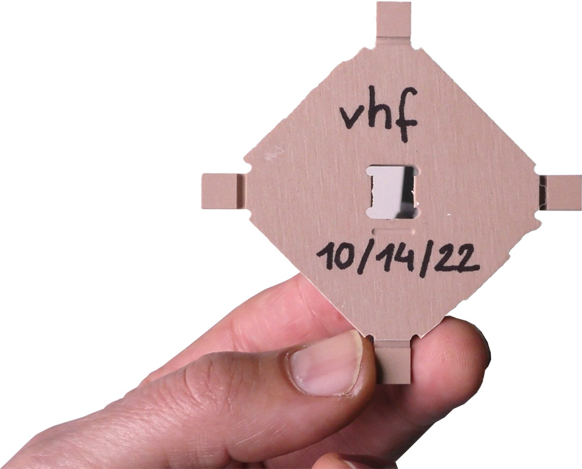
Remove the test specimen from the machine.
-
Recommendation: Label the test specimen with a name and date.

-
To ensure accurate measurement results, remove all manufacturing residues with a brush.
-
Recommendation Put the individual parts onto a flat surface so that you can use both hands to handle the micrometer.
-
Measure the test specimen.
- Measure each position 2 times.
-
Record all measuring values.
-
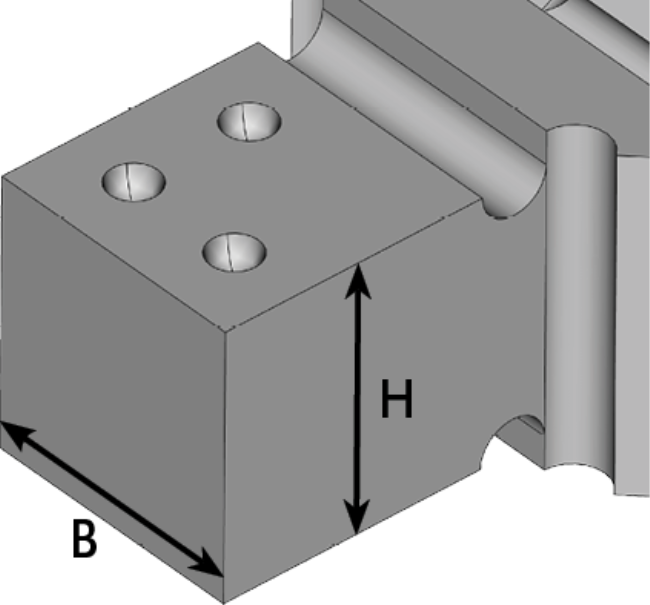
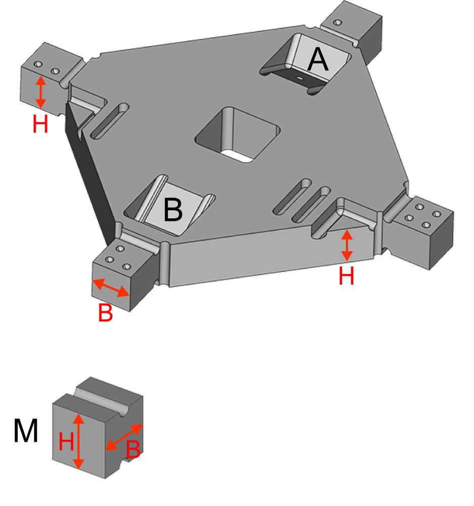
Measure the height of the measurement points that begin with H.
Number of measurement points: 2
-
Measure the width of the measurement points that begin with B.
Number of measurement points: 4
-
Compare the measuring values with the following table.
(Optional) In addition to the manual check, use the machine-specific interactive form.
-
If all measuring values are within the range of tolerance, a calibration is not necessary. Otherwise, manufacture and measure a calibration specimen.
-
Remove the test specimen from the machine.
-
Recommendation: Label the test specimen with a name and date.
-
To ensure accurate measurement results, remove all manufacturing residues with a brush.
-
Recommendation Put the individual parts onto a flat surface so that you can use both hands to handle the micrometer.
-
Measure the test specimen.
- Measure each position 2 times.
-
Record all measuring values.
-
Compare the measuring values with the following table.
(Optional) In addition to the manual check, use the machine-specific interactive form.
-
If all measuring values are within the range of tolerance, a calibration is not necessary. Otherwise, manufacture and measure a calibration specimen.
-
Remove the test specimen from the machine.
-
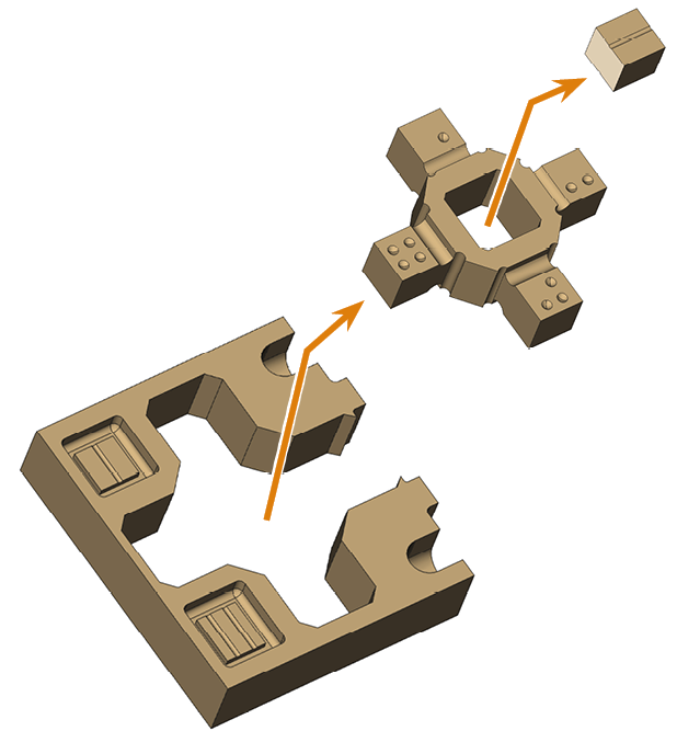
Separate the parts.
-
Recommendation: Label the test specimen with a name and date.
-
To ensure accurate measurement results, remove all manufacturing residues with a brush.
-
Recommendation Put the individual parts onto a flat surface so that you can use both hands to handle the micrometer.
-
Measure the test specimen.
- Measure each position 2 times.
-
Record all measuring values.
-
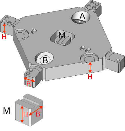
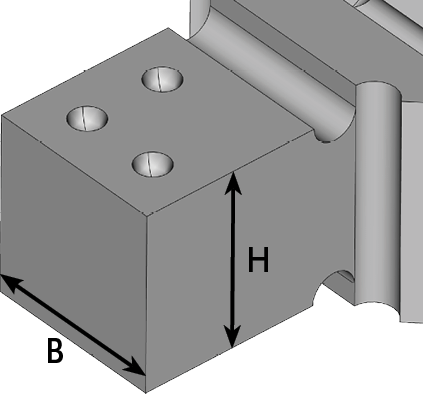
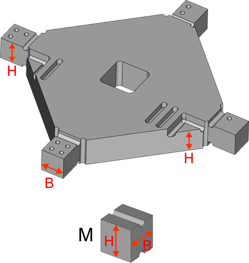
Measure the width and height of the measurement points, which are marked with circles.
Number of measurement points: 4
-
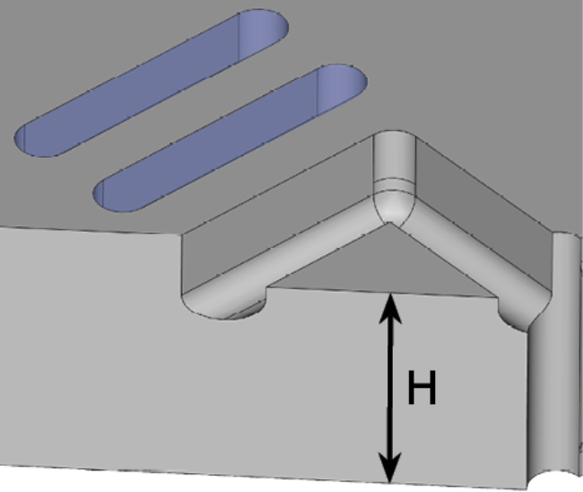
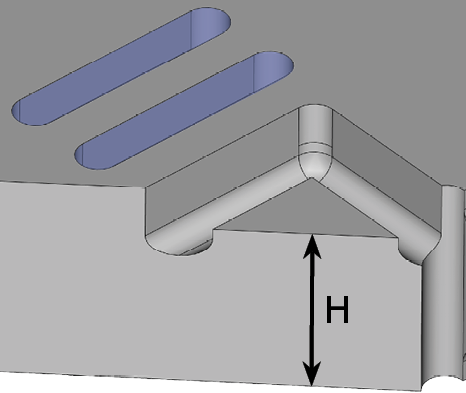
Measure the heights of the triangles marked with bars.
Number of measurement points: 2
-
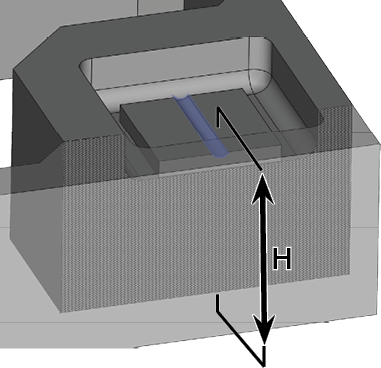
Measure the width and the height of the cube M.
- Measure the height and width as shown in the following figure.
-
When measuring the width, place the micrometer at the top of the cube (area marked in green).
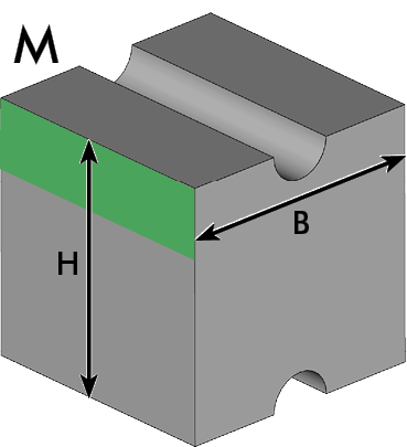
-
Compare the measuring values with the following table.
(Optional) In addition to the manual check, use the machine-specific interactive form.
-
If all measuring values are within the range of tolerance, a calibration is not necessary. Otherwise, manufacture and measure a calibration specimen.
-
Remove the test specimen from the machine.
-
Separate the parts.
-
Recommendation: Label the test specimen with a name and date.
-
To ensure accurate measurement results, remove all manufacturing residues with a brush.
-
Recommendation Put the individual parts onto a flat surface so that you can use both hands to handle the micrometer.
-
Measure the test specimen.
- Measure each position 2 times.
-
Record all measuring values.
-
Measure the width and height of the measurement points, which are marked with circles.
Number of measurement points: 4
-
Measure the heights of the triangles marked with bars.
Number of measurement points: 2
-
Measure the width and the height of the cube M.
- Measure the height and width as shown in the following figure.
-
When measuring the width, place the micrometer at the top of the cube (area marked in green).
-
Compare the measuring values with the following table.
(Optional) In addition to the manual check, use the machine-specific interactive form.
-
If all measuring values are within the range of tolerance, a calibration is not necessary. Otherwise, manufacture and measure a calibration specimen.
-
Remove the test specimen from the machine.
-
Separate the parts.
-
Recommendation: Label the test specimen with a name and date.
-
To ensure accurate measurement results, remove all manufacturing residues with a brush.
-
Recommendation Put the individual parts onto a flat surface so that you can use both hands to handle the micrometer.
-
Measure the test specimen.
- Measure each position 2 times.
-
Record all measuring values.
-
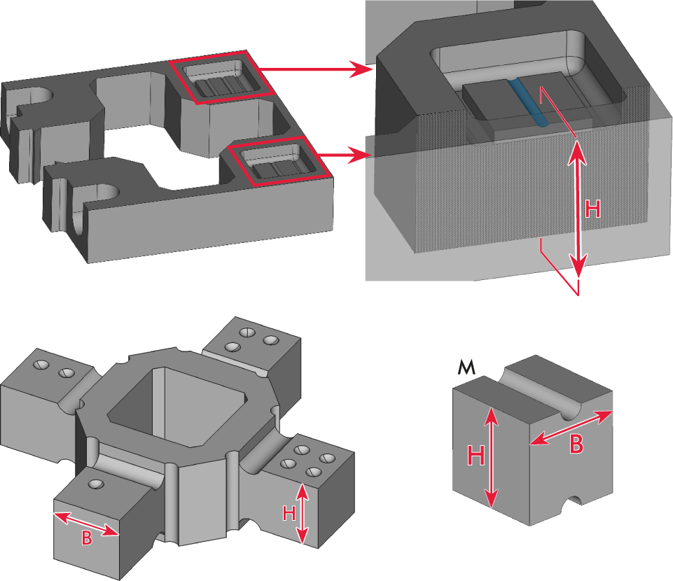
Measure the heights of the triangles marked with bars.
Number of measurement points: 2
-
Measure the height of the inner blocks marked with bars.
Number of measurement points: 2
-
Measure the width and the height of the cube M.
- Measure the height and width as shown in the following figure.
-
When measuring the width, place the micrometer at the top of the cube (area marked in green).
-
Compare the measuring values with the following table.
(Optional) In addition to the manual check, use the machine-specific interactive form.
-
If all measuring values are within the range of tolerance, a calibration is not necessary. Otherwise, manufacture and measure a calibration specimen.
-
Remove the test specimen from the machine.
-
Separate the parts.
-
Recommendation: Label the test specimen with a name and date.
-
To ensure accurate measurement results, remove all manufacturing residues with a brush.
-
Recommendation Put the individual parts onto a flat surface so that you can use both hands to handle the micrometer.
-
Measure the test specimen.
- Measure each position 2 times.
-
Record all measuring values.
-
Measure the width and height of the measurement points, which are marked with circles.
Number of measurement points: 4
-
Measure the heights of the triangles marked with bars.
Number of measurement points: 2
-
Measure the width and the height of the cube M.
- Measure the height and width as shown in the following figure.
-
When measuring the width, place the micrometer at the top of the cube (area marked in green).
-
Compare the measuring values with the following table.
(Optional) In addition to the manual check, use the machine-specific interactive form.
-
If all measuring values are within the range of tolerance, a calibration is not necessary. Otherwise, manufacture and measure a calibration specimen.
Example:
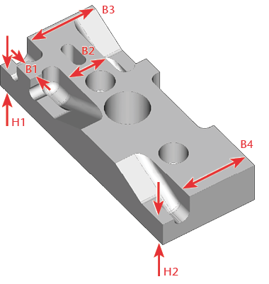
| Measuring position | Value |
|---|---|
|
H1 |
5.85 mm – 6.15 mm |
|
H2 |
5.85 mm – 6.15 mm |
|
B1 |
4.92 mm – 5.08 mm |
|
B2 |
9.92 mm – 10.08 mm |
|
B3 & B4 |
Difference: max. 0.2 mm |
Example:
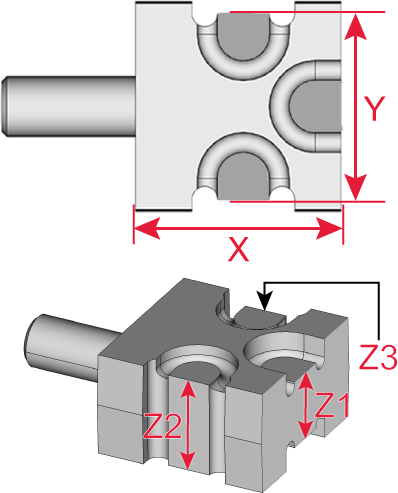
| Measuring position | Value |
|---|---|
|
X |
19.95 mm – 20.05 mm |
|
Y |
17.95 mm – 18.05 mm |
|
Z1 |
7.95 mm – 8.05 mm |
|
Z2 & Z3 |
Difference max. 0.1 mm |
Example:
ATTENTION! Incorrect measuring values due to an error in measuring the M cube
| Measuring position | Width | Height |
|---|---|---|
|
Cube ● |
7.95 mm – 8.05 mm |
7.95 mm – 8.05 mm |
|
Cube ●● |
7.95 mm – 8.05 mm |
7.95 mm – 8.05 mm |
|
Cube ●●● |
7.95 mm – 8.05 mm |
7.95 mm – 8.05 mm |
|
Cube ●●●● |
7.95 mm – 8.05 mm |
7.95 mm – 8.05 mm |
|
Cube M |
7.95 mm – 8.05 mm |
7.95 mm – 8.05 mm |
|
Triangle | and Triangle || |
– |
Difference max. 0.1 mm |
Example:
ATTENTION! Incorrect measuring values due to an error in measuring the M cube
| Measuring position | Width | Height |
|---|---|---|
|
Cube ● |
7.95 mm – 8.05 mm |
7.95 mm – 8.05 mm |
|
Cube ●● |
7.95 mm – 8.05 mm |
7.95 mm – 8.05 mm |
|
Cube ●●● |
7.95 mm – 8.05 mm |
7.95 mm – 8.05 mm |
|
Cube ●●●● |
7.95 mm – 8.05 mm |
7.95 mm – 8.05 mm |
|
Cube M |
7.95 mm – 8.05 mm |
7.95 mm – 8.05 mm |
|
Block | and Block || |
Difference max. 0.1 mm |
|
Example:
ATTENTION! Incorrect measuring values due to an error in measuring the M cube
| Measuring position | Width | Height |
|---|---|---|
|
Cube ● |
7.95 mm – 8.05 mm |
7.95 mm – 8.05 mm |
|
Cube ●● |
7.95 mm – 8.05 mm |
7.95 mm – 8.05 mm |
|
Cube ●●● |
7.95 mm – 8.05 mm |
7.95 mm – 8.05 mm |
|
Cube ●●●● |
7.95 mm – 8.05 mm |
7.95 mm – 8.05 mm |
|
Cube M |
7.95 mm – 8.05 mm |
7.95 mm – 8.05 mm |
|
Triangle | and Triangle || |
– |
Difference max. 0.1 mm |