Calibrating the machine with calibration specimens
June 2023: Note the modified measurement of the cube M for test and calibration specimens.
If the machining results are no longer satisfactory, a calibration of the machine may improve them. Calibration includes manufacturing test and calibration specimens with your machine and measuring them.
Deterioration of machining results caused by an incorrect calibration
At delivery, your machine is already calibrated. As long as your machining results are accurate, a new calibration is not necessary. A calibration takes much time and will deteriorate the machining results if it is improperly executed.
- If the machining results are inaccurate, try adjusting the machining conditions first: Check the fixation and quality of the blank and the condition of the tool.
- Before calibrating the machine, contact customer service.
- Be very careful when measuring and entering data during calibration. When in doubt, abort the calibration.
-
Open the DentalCNC Application settings with the following icon in the main icon bar:

-
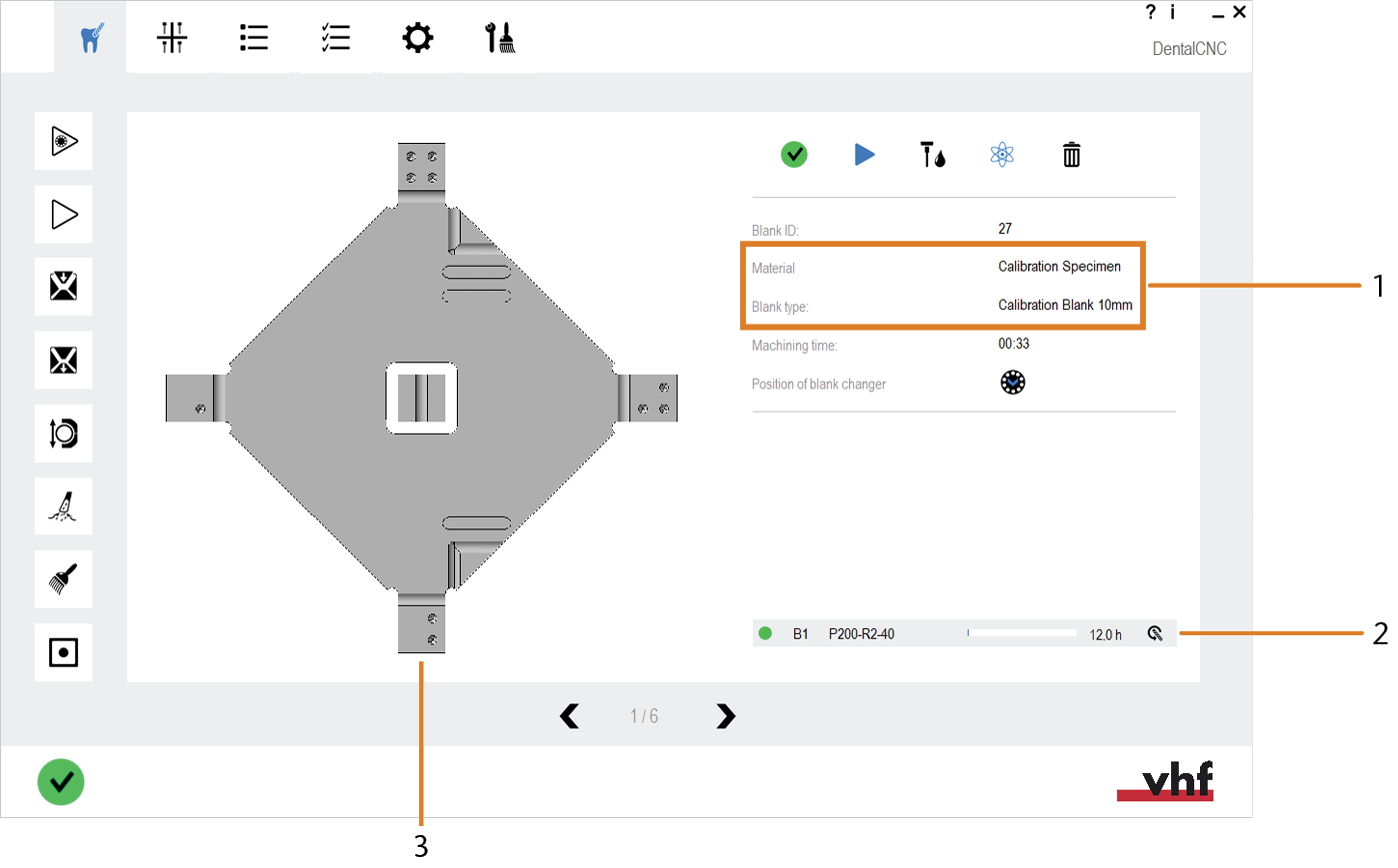
Open the Machine maintenance view with the following icon in the local icon bar:

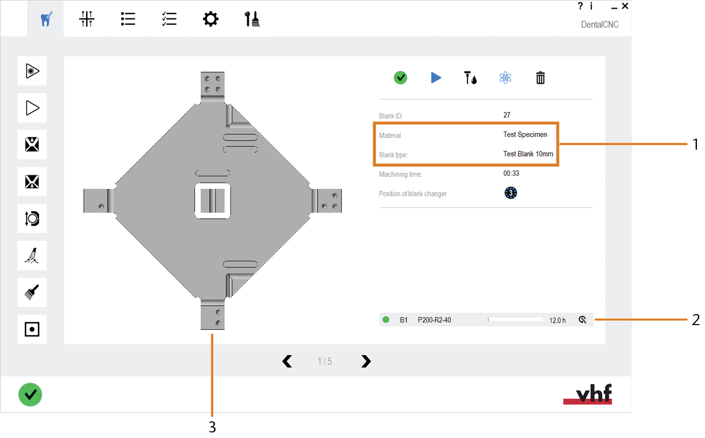
![]()
The Machine maintenance view; icons for calibrating the machine marked orange
General information on calibration
Mind the difference between test specimens and calibration specimens
Test specimens and calibration specimens differ in shape and functionality:
-
Test specimens are used to test if the machine needs to be calibrated.
-
Calibration specimens are used to calibrate the machine.
Calibration workflow:
-
Have the calibration set readily available
The set was provided with your machine.
-
Manufacture and measure a test specimen
If the measuring values are within tolerance, your machine mechanics are accurate and you do not need to calibrate the machine. If they are out of tolerance, continue with calibrating the machine.
-
Manufacture and measure a calibration specimen and enter the measuring values into DentalCNC.
This data is used to calculate the required calibration.
-
Check if calibration was successful with another test specimen
Verify that the calibration has improved the machining results.
Instruments for measuring test and calibration specimens
To measure the calibration or test specimen, you need to use a micrometer.
-
NOTICE! Never use common measuring instruments such as rulers or calipers for measuring calibration or test specimens. These instruments are too imprecise for this task.
Tools for milling calibration and test specimens
| Machine | Tool |
|---|---|
|
E3 |
P300-R2-60 |
|
E4 |
P250-F1-40-T P200-R1-40 |
|
E5 |
P250-F1-40-T |
|
K5, K5+ R5 S1, S2, S5 |
P200-R1-40 |
|
K4 edition N4, N4+ |
P200-R1-35 |
|
Z4 |
P200-R1-35 |
Other machines are not supported by DentalCAM & DentalCNC 8.
Step 1: Preparing calibration for E5machines
-
Check the machine serial number.
Per identification plate: Identification plate and serial number
Per DentalCNC: Machine serial number, product key and control unit serial number
-
Serial number ≤ E5ID5…:
-
Switch off the machine for at least 2 hours.
-
For best results, ensure an ambient temperature of 18 – 25 °C.
-
Step 2: Have the calibration set readily available
You received a calibration set with your machine which consists of the following components:
- Designated blanks from which the calibration and test specimens are milled
- A designated tool for machining calibration and test specimens
- A micrometer for measuring the calibration and test specimens
Watch the video
YouTube video – When viewing this video, personal data is sent to YouTube, LLC, USA. Privacy statement
Step 3: Manufacture and measure a test specimen
Watch the video
YouTube video – When viewing this video, personal data is sent to YouTube, LLC, USA. Privacy statement
Manufacturing a test specimen
Create orders for calibration and test specimens directly in DentalCNC and not with DentalCAM.
- In the Machine maintenance view, select the following icon in the left column:

-
DentalCNC opens the Machining view and adds a job for the test specimen to the job list.
-
Select the job you created in step 1.
- The job details display.
- Labels designating the specimen
- Required tool to mill the specimen
- Preview of the milled specimen
- Prepare the machine as follows:
Mount/load the calibration blank into the working chamber.
R5: Mount the blank directly into the working chamber.
Insert the calibration tool into the tool magazine of your machine and into the virtual tool magazine in DentalCNC.
- Machine the job like any other job.
- The machine manufactures the specimen.
- Continue with measuring the specimen.
Example of displayed values and graphics
Measuring the test specimen
Depending on the machine-specific specimen, the following measuring points exist:
-
Cubes
-
Triangles
-
Blocks
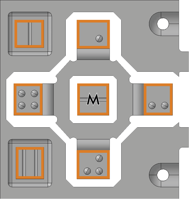
Most measuring points on the specimen are marked with icons:
- Circles (represented in this document as ●)
- Bars (represented in this document as |)
- Letters, numbers (e.g., A, Z1)
The cube in the middle of most specimens is the measuring points M (referred to as 'cube M').
Pictures of test specimens of all machines
Test specimen for the E5
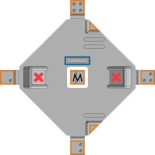
Test specimen for the S series, K5, K5+
Test specimen for the K4 edition, R5
Test and calibration specimen for the N4, N4+
Test and calibration specimen for the Z4
Test and calibration specimen for the E4
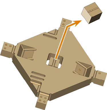
Test and calibration specimen for the E3
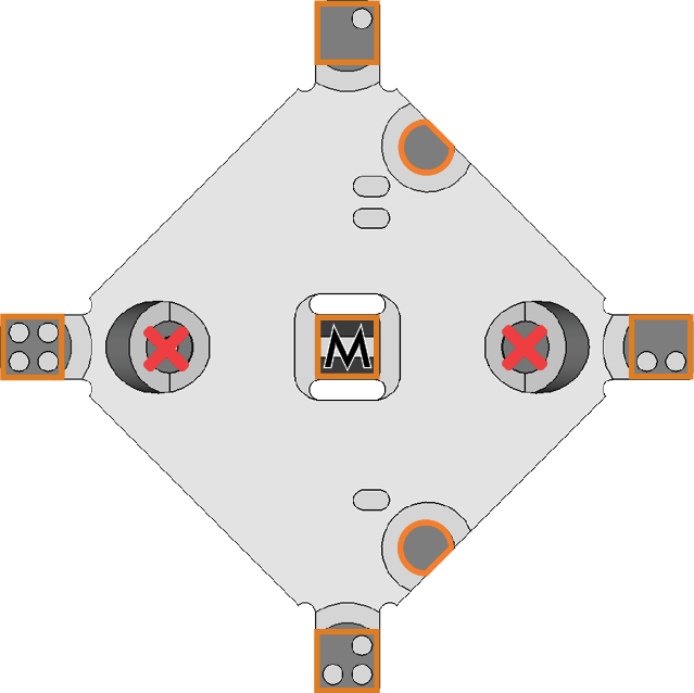
-
Orange markings, arrows: Measuring points
-
Blue marking: Marking on the specimen which indicates a test specimen (not for all machines)
-
Red crosses: Points that can be ignored when measuring a test specimen
Procedure
-
Remove the test specimen from the machine.
-
Separate the parts of the following test specimens as shown:
-
For correct measurement results, remove all machining residues from the test or calibration specimen with a small brush.
-
(Recommended) Put the individual parts of the specimen onto a flat surface so that you can use both hands to handle the micrometer.
-
Check if the zero point of the micrometer is set correctly.
-
Measure the measuring points of the machine-specific specimen:
-
Enter the measuring values in the machine-specific test table under step 7.
Alternative: Record each measuring value on a piece of paper.
-
(Recommended) Label the body with a name and date (e.g., “
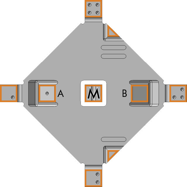
The measuring points of the machine-specific bodies:
-
-
Ignore the slanted surfaces (A, B) as they are only required for calibration.
-
Measure the width and height of the measuring points, which are labeled with circles.
-
Measure the height of the measuring points which are labeled with bars.
-
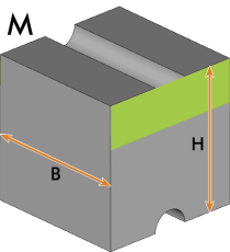
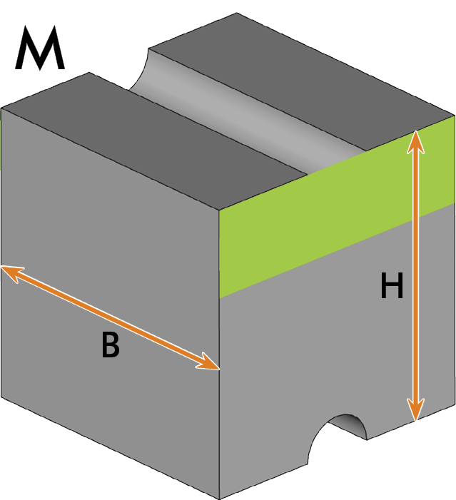
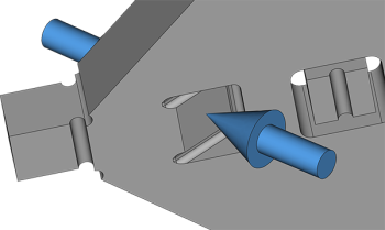
Measure the width and the height of the cube M.
- Measure the height and width as shown in the following figure.
-
When measuring the width, place the micrometer at the top of the cube (area marked in green).
-
Measure the width and height of the measuring points, which are labeled with circles.
-
Measure the height of the measuring points which are labeled with bars.
-
Measure the width and the height of the cube M.
- Measure the height and width as shown in the following figure.
-
When measuring the width, place the micrometer at the top of the cube (area marked in green).
-
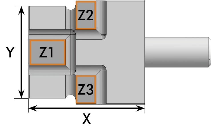
Measure the length of the line segments X and Y.
-
Measure the height of Z1, Z2, Z3.
-
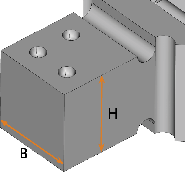
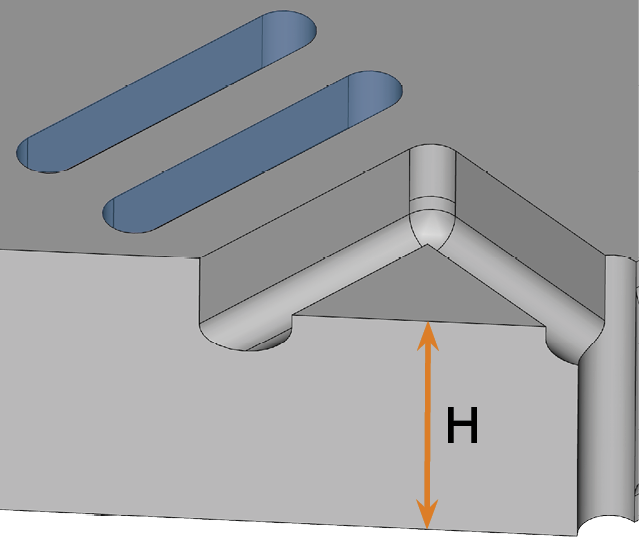
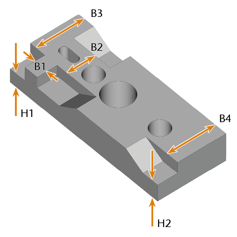
Measure the height of the measuring points that begin with H.
-
Measure the width of the measuring points that begin with B.
-
Check if you need to calibrate the machine by comparing the measuring values with the values in the machine-specific table.
Optionally and in addition to the manual check, use the machine-specific interactive form.
-
If all measuring values are withing the range of tolerance, a calibration is not necessary. Otherwise, continue with machining and measuring a calibration specimen.
E5, K4 edition, K5, K5+, R5, S1, S2, S5
Bars labeling the triangle marked blue
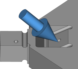
NOTICE! Incorrect measurement results, if you apply the micrometer incorrectly to the M cube
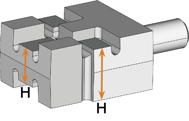
N4, N4+
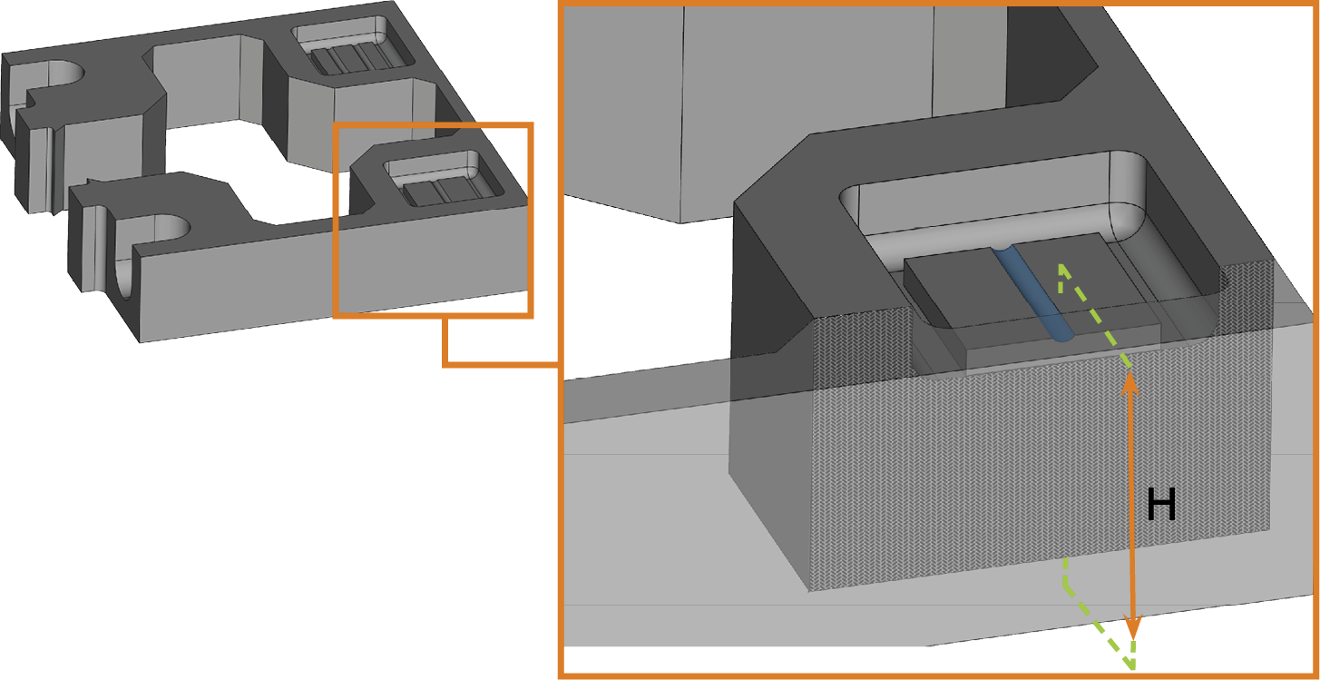
Measuring the height of a cube labeled with a bar (marked blue)
NOTICE! Incorrect measurement results if you place the outside micrometer at the bottom of the cube M when measuring the width
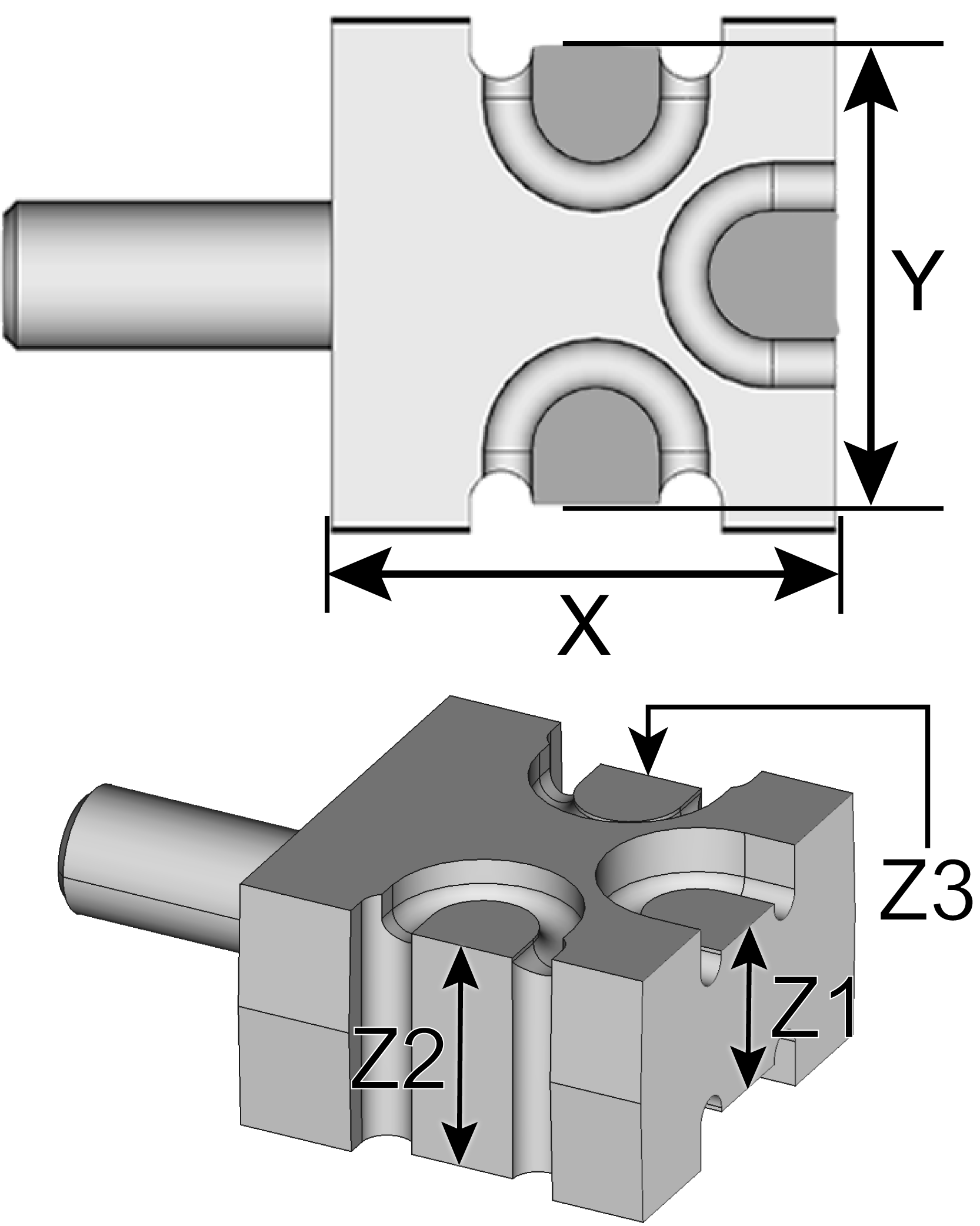
E4, Z4
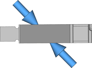
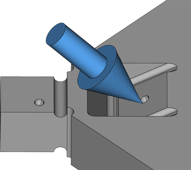
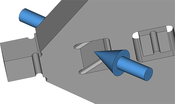
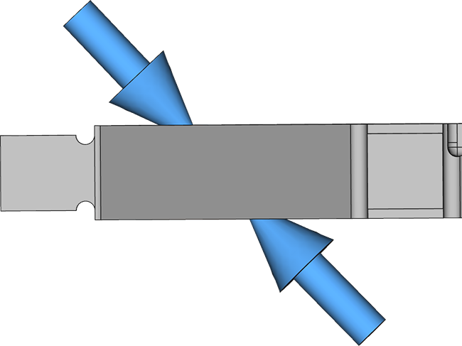
The test and calibration specimen of the Z4
The test and calibration specimen of the E4
Z4: Measure the height of Z1 (left arrow) and Z3 (right arrow); Z2 in analogy to Z3
E4
E3
E5, K4 edition, K5, K5+, R5, S1, S2, S5
Surfaces A and B are used for calibration only
| Measuring position | Width | Height |
|---|---|---|
|
Cube ● |
7.95 mm – 8.05 mm |
7.95 mm – 8.05 mm |
|
Cube ●● |
7.95 mm – 8.05 mm |
7.95 mm – 8.05 mm |
|
Cube ●●● |
7.95 mm – 8.05 mm |
7.95 mm – 8.05 mm |
|
Cube ●●●● |
7.95 mm – 8.05 mm |
7.95 mm – 8.05 mm |
|
Cube M |
7.95 mm – 8.05 mm |
7.95 mm – 8.05 mm |
|
Triangle | and Triangle || |
– |
Difference max. 0.1 mm |
Example: The values “Triangle | 7.151 mm” and “Triangle || 7.195 mm” differ by less than 0.1 mm (difference:0.044 mm) and are thus within tolerance.
The values “Triangle | 6.845 mm” and “Triangle || 6.946 mm” differ by more than 0.1 mm (difference: 0.101 mm) and are thus out of tolerance.
N4, N4+
| Measuring position | Width | Height |
|---|---|---|
|
Cube ● |
7.95 mm – 8.05 mm |
7.95 mm – 8.05 mm |
|
Cube ●● |
7.95 mm – 8.05 mm |
7.95 mm – 8.05 mm |
|
Cube ●●● |
7.95 mm – 8.05 mm |
7.95 mm – 8.05 mm |
|
Cube ●●●● |
7.95 mm – 8.05 mm |
7.95 mm – 8.05 mm |
|
Cube M |
7.95 mm – 8.05 mm |
7.95 mm – 8.05 mm |
|
Block | and Block || |
Difference max. 0.1 mm |
|
Example: The values “Block | 7.151 mm” and “Block|| 7.195 mm” differ by less than 0.1 mm (difference: 0.044 mm) and are thus within tolerance.
The values “Block | 6.845 mm” and “Block || 6.946 mm” differ by more than 0.1 mm (difference: 0.101 mm) and are thus out of tolerance.
E4, Z4
| Measuring position | Value |
|---|---|
|
X |
19.95 mm–20.05 mm |
|
Y |
17.95 mm–18.05 mm |
|
Z1 |
7.95 mm – 8.05 mm |
|
Z2 & Z3 |
Difference max. 0.1 mm |
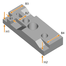
E3
| Measuring position | Value |
|---|---|
|
H1 |
5.85 mm – 6.15 mm |
|
H2 |
5.85 mm – 6.15 mm |
|
B1 |
4.92 mm – 5.08 mm |
|
B2 |
9.92 mm – 10.08 mm |
|
B3 and B4 |
Difference: max. 0.2 mm |
Step 4: Manufacture calibration specimens, measure them and enter measured values in DentalCNC
Watch the video
YouTube video – When viewing this video, personal data is sent to YouTube, LLC, USA. Privacy statement
Manufacturing a calibration specimen
- In the Machine maintenance view, select the following icon in the left column:

-
DentalCNC opens the Machining view and adds a job for the calibration specimen to the job list.
-
Select the job you created in step 1.
- The job details display.
- Labels designating the specimen
- Required tool to mill the specimen
- Preview of the milled specimen
- Prepare the machine as follows:
Mount/load the calibration blank into the working chamber.
R5: Mount the blank directly into the working chamber.
Insert the calibration tool into the tool magazine of your machine and into the virtual tool magazine in DentalCNC.
- Machine the job like any other job.
- The machine manufactures the specimen.
- Continue with measuring the specimen.
Example of displayed values and graphics
Measuring the calibration specimen
Depending on the machine-specific specimen, the following measuring points exist:
-
Cubes
-
Triangles
-
Blocks
Most measuring points on the specimen are marked with icons:
- Circles (represented in this document as ●)
- Bars (represented in this document as |)
- Letters, numbers (e.g., A, Z1)
The cube in the middle of most specimens is the measuring points M (referred to as 'cube M').
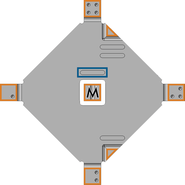
Pictures of calibration specimens of all machines
Calibration specimen for the E5
Calibration specimen for the S series, K5, K5+
Calibration specimen for the K4 edition, R5
Test and calibration specimen for the N4, N4+
Test and calibration specimen for the Z4
Test and calibration specimen for the E4
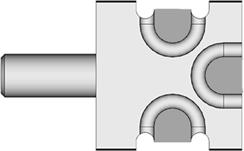
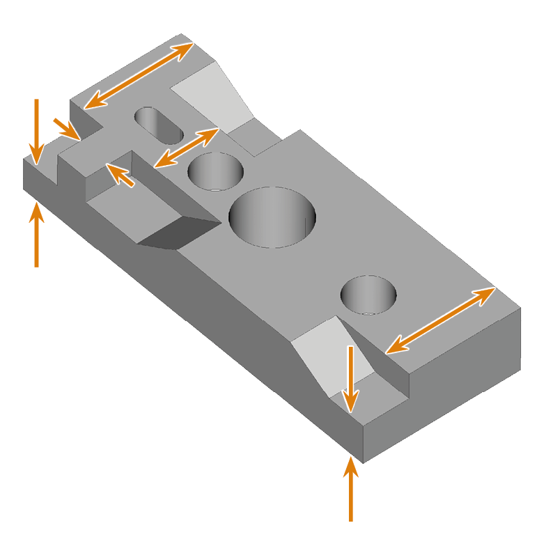
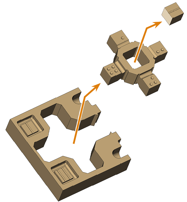
Test and calibration specimen for the E3
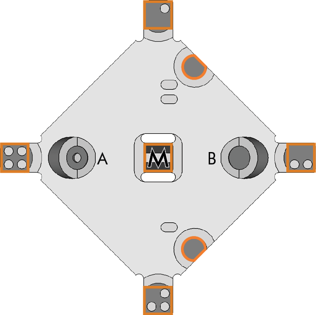
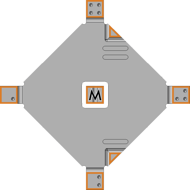
-
Orange markings, arrows: Measuring points
-
A, B: Measure only under certain conditions (see instructions below)
Procedure
-
Remove the calibration specimen from the machine.
-
Separate the parts of the following calibration specimens as shown:
-
For correct measurement results, remove all machining residues from the test or calibration specimen with a small brush.
-
(Recommended) Put the individual parts of the specimen onto a flat surface so that you can use both hands to handle the micrometer.
-
Check if the zero point of the micrometer is set correctly.
-
Measure the measuring points of the machine-specific specimen:
-
Enter the values directly in DentalCNC.
-
(Recommended) Label the body with a name and date (e.g., “
The measuring points of the machine-specific bodies:
-
-
Measure the width and height of the measuring points, which are labeled with circles.
-
Measure the height of the measuring points which are labeled with bars.
-
Measure the width and the height of the cube M.
- Measure the height and width as shown in the following figure.
-
When measuring the width, place the micrometer at the top of the cube (area marked in green).
-
(K5, K5+, S1, S2, S5) Measure the distance between the opposite inclined surfaces:
There are 2 pairs of this surface (A, B) that you need to measure.
-
The inclined surface A is marked with a dot on the upper side of the calibration specimen.
-
The inclined surface B is not marked.
Inclined surface A with point on the upper side
-
-
Measure the width and height of the measuring points, which are labeled with circles.
-
Measure the height of the measuring points which are labeled with bars.
-
Measure the width and the height of the cube M.
- Measure the height and width as shown in the following figure.
-
When measuring the width, place the micrometer at the top of the cube (area marked in green).
-
Measure the length of the line segments X and Y.
-
Measure the height of Z1, Z2, Z3.
-
Measure the height of the measuring points that begin with H.
-
Measure the width of the measuring points that begin with B.
-
Continue with entering the measuring values into DentalCNC.
E5, K4 edition, K5, K5+, R5, S1, S2, S5
Bars labeling the triangle marked blue
NOTICE! Incorrect measurement results, if you apply the micrometer incorrectly to the M cube
N4, N4+
Measuring the height of a cube labeled with a bar (marked blue)
NOTICE! Incorrect measurement results if you place the outside micrometer at the bottom of the cube M when measuring the width
E4, Z4
The test and calibration specimen of the Z4
The test and calibration specimen of the E4
Z4: Measure the height of Z1 (left arrow) and Z3 (right arrow); Z2 in analogy to Z3
E4
E3
Enter measuring values of the calibration specimen in DentalCNC
-
NOTICE! Never enter measuring values of a test specimen into DentalCNC. This leads to an incorrect calibration and imprecise manufacturing results.
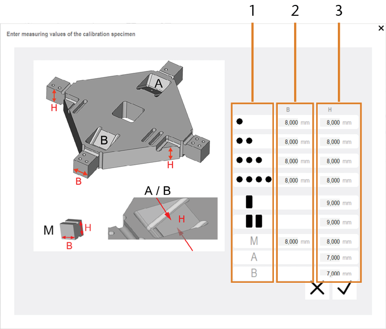
Enter calibration values (S series, K5, K5+)
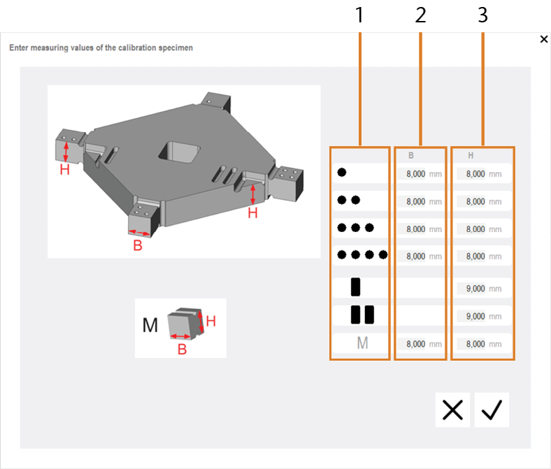
Entering calibration values (K4 edition, R5)
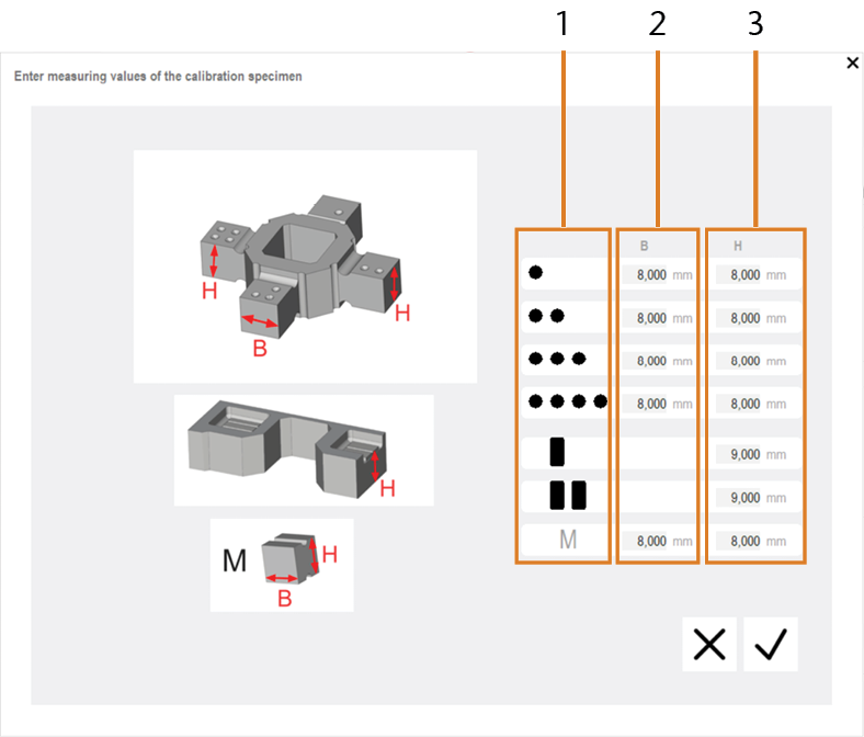
Entering calibration values (N4, N4+)
-
Icons for measuring points
-
Input fields for the width of the measuring point
-
Input fields for the height of the measuring point
Icons for measuring points

Circles

Bar

Cube M

Measuring points labeled with letters and numbers
- Enter the measuring values of the calibration specimen:
- Enter the height of the measuring points Z1, Z2, Z3.
- Enter the length of the line segment X, Y.
- Enter the height and width of all measuring points which are labeled with circles.
- Enter the height values of all measuring points which are labeled with bars.
- Enter the height and width value of the cube M.
- S1, S2, S5, K5, K5+: If a new Y end switch or ball screw drive was installed, enter the height values of the slanted surfaces A, B.
- To confirm your input, select the following icon:

- The current window closes. A dialog window opens.
- Confirm the current message.
E4, Z4
Other machines
Step 5: Checking the calibration
-
Mill and measure a test specimen. Verify that the measuring values are within tolerance. Manufacture and measure a test specimen
-
If the measuring values are within tolerance, the calibration was successful.