Use the object viewer

Using the object viewer, you can view and visually inspect STL files before importing them. The object viewer also analyzes issues with the 3D mesh of objects, allowing you to identify non-manifold geometries, for example.
Open the object viewer and load STL files
-
Drag the object file into the Examine object area.
Alternative: Open the file browser via the Open object button and select the desired file.
-
dentalcam displays the object’s 3D geometry.
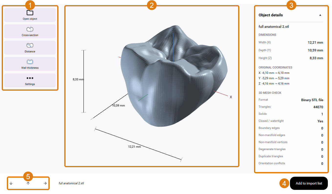
1
Buttons for functions
2
Object display
3
Object information column
4
Button to add the object to the import list
5
Icons for selecting the perspective
Display cross-section
You can display a cross-section of the object. The object file is not modified in the process.
-
Select the
 Cross-section button.
-
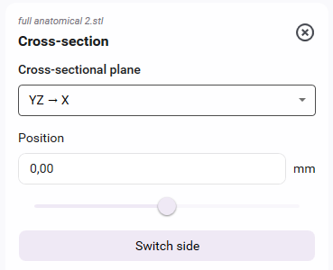
dentalcam displays the corresponding control elements in the 2nd column.
-
From the Cutting plane drop-down list, select the angle at which the cutting plane should intersect the object.
-
To rotate the cross-section by 180°, select the Switch side button.
-
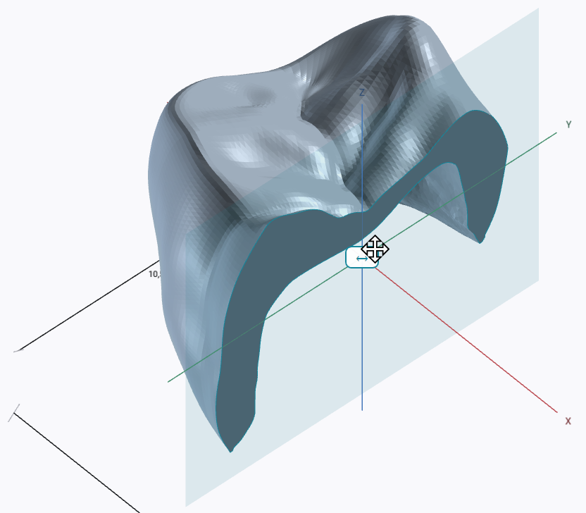
Move the cut as desired:
-
Via the Position input field.
-
Via the slider below the input field.
-
By moving the following icon in the object display:

-
Measure distances
You can measure the distance between 2 points.
-
Select the
 Distance button.
-
dentalcam displays the corresponding control elements in the 2nd column.
-
Select 2 points on the object surface.
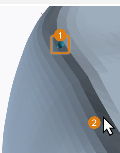
The 1st measurement point has already been set; the 2nd measurement point is currently being set
-
dentalcam adds the measuring value to the object display and the list.
-
To delete 1 measuring value, mark the entry in the list of measuring values and click the Remove selected button.
-
To remove all measuring values, select the Remove all measurements button.
Measure wall thicknesses
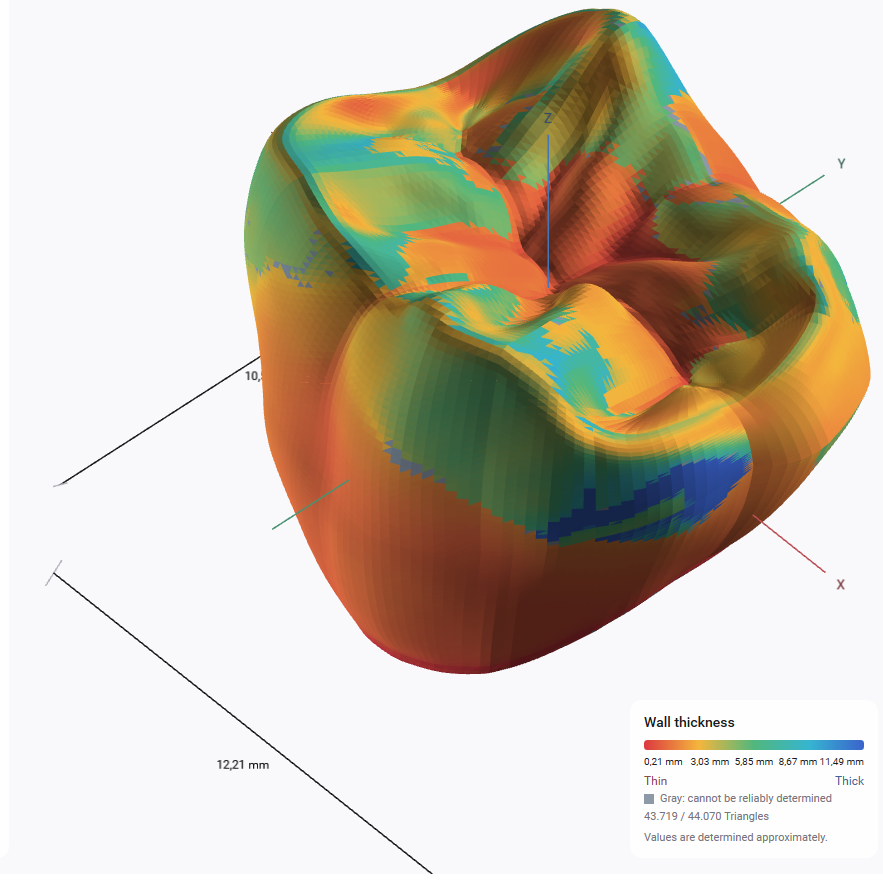
You can measure the wall thickness individually at any point on the surface or display the wall thicknesses of the entire surface as a color chart. You can use the color values to identify areas that could be critical for manufacturing.
-
Select the
 Wall thickness button.
-
dentalcam displays the corresponding control elements in the 2nd column.
-
To set 1 measurement point, select 1 point on the object’s surface.
-
dentalcam adds the measuring value to the object display and the list.
-
To delete 1 measuring value, mark the entry in the list of measuring values and click the Remove selected button.
-
To remove all measuring values, select the Remove all measurements button.
-
Activate the Display wall thickness color chart check box.
-
Wall thicknesses are displayed color-coded on the object’s surface.
-
dentalcam displays a legend for the color values in the object view.
-
Until you uncheck the box, the color chart will remain displayed even after you exit the current function.
-
Check 3D mesh
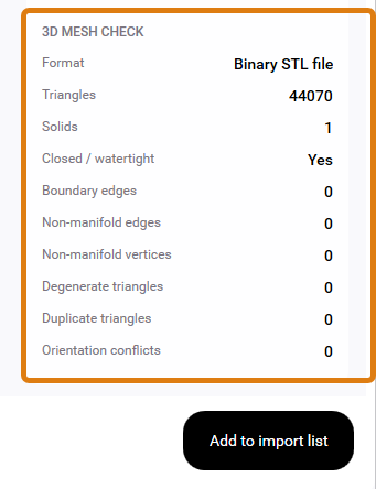
When loading an object file, the object viewer automatically analyzes the 3D mesh for errors.
-
Check the values displayed in the object information column under the 3D MESH CHECK heading. To do this, use the information in the Help Article Requirements for STL files.
Add objects to import list
If the object is suitable for manufacturing, you can add it to the import list directly from the object viewer and continue with the main workflow.
-
Select the Add to import list button.
-
dentalcam adds the object to the import list and switches to the Object import workflow step.
-


