Marking drill holes and deleting markings
Drill holes must be marked to ensure optimal manufacturing of the object. Incorrectly marked and unmarked drill holes must be marked manually with the Drill holes editing function.
Requirement You are editing a blank in the Nesting view using appropriate objects.
-
Activate the top view with
 .
-
Select the desired object in the blank display.
-
Open the Mark drill holes editing function with
 .
-
-
Use and to switch between the individual editing steps.
-
You can discard all changes with
 any time and close the editing function.
-
-
If you want to delete a marking:
-
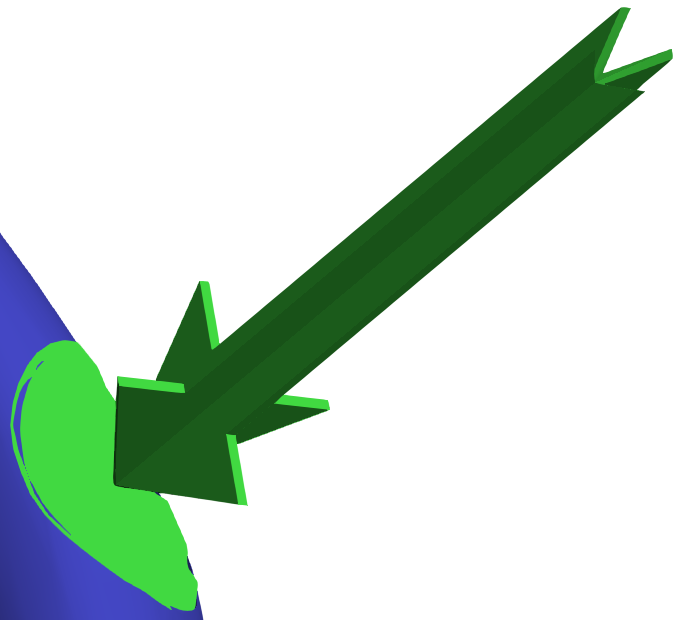
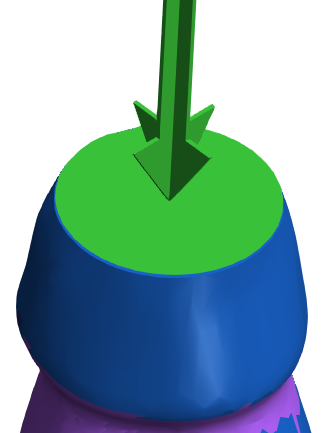
Select the arrow of the drill hole in the blank display.
Alternative: Select the desired entry from the list of marked drill holes.
-
dentalcam highlights the entry in the list with a blue border.
-
Delete the marking with
 .
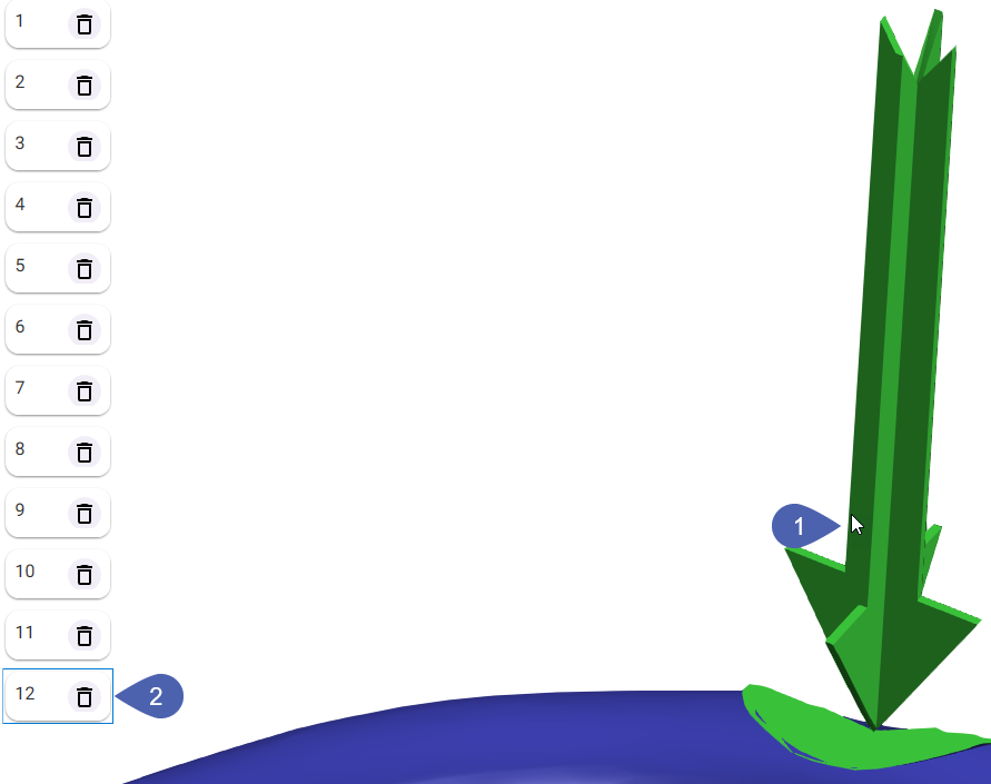
-
-
Look down at the end of the drill hole from above.
-
You must be able to see a good portion of the wall of the drill hole.
-
Zoom in on the object as shown in the following figure.
-
Click here to proceed to the next editing step.
-
Mark 3 measurement points next to each other on the inner wall of the drill hole.
-
Space the measurement points out a bit.
-
The measurement points must not be located on a connection geometry or torsion protection.
Examples: 2 measurement points have already been set. The third point is placed at the cursor's position. The orange arrow indicates the drilling direction.
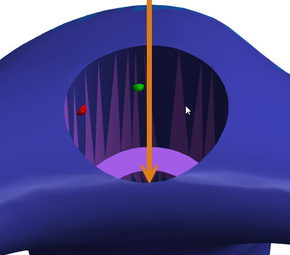
Setting measurement points for a simple drill hole
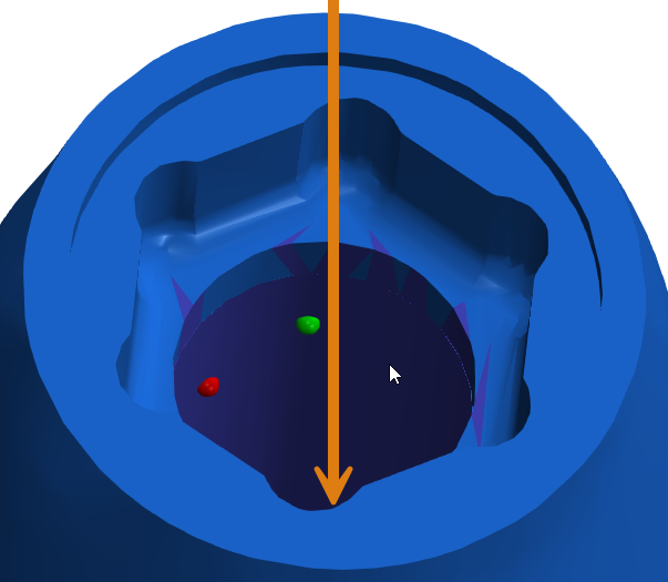
Setting measurement points for a drill hole in an abutment with connection geometry and inner edge
-
-
Click here to proceed to the next editing step.
-
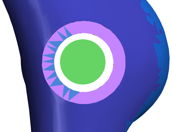
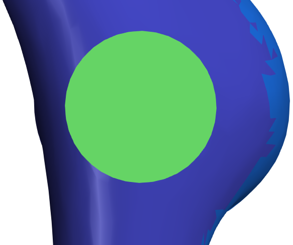
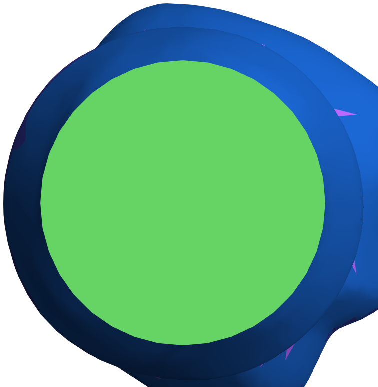
dentalcam displays the diameter of the drilling range as a green circle.
-
Use the value bar or the input field to set the diameter of the drilling range.

-
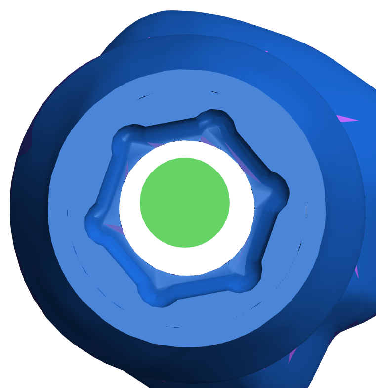
The drilling range must be slightly larger than the opening of the drill hole.
-
Connection geometries and inner edges are considered part of the opening.
-
-
Save the marking with OK.
-
Check that the marking is correct. If the marking is incorrect, start again from step 5.
-
Mark the other end of the drill hole and all other drill holes as described.
-
Save all changes with
.Do not use
. -
dentalcam closes the editing function.
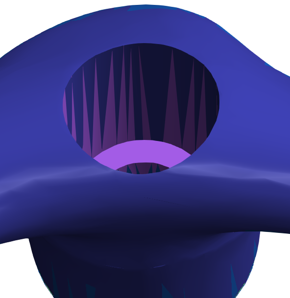
Example: Simple drill hole
Example: Drill hole in an abutment with connection geometry and inner edge
What's next?
If the object has unidentified or incorrectly marked cavities, mark them:
Marking cavities and deleting markings
To complete the nesting for the object, set the bars:
All nesting information and activities:


