Creating new jobs
A job contains all the data required for trimming one or more dental splints: 3D data, base and trim parameters, calculated milling path, etc.
Step 1: Create the job
You create a new job in the start page of trimcam.
-
Select New job.
-
Give the job a name via the input field Name of job:.
The name may not contain any umlauts or special characters. -
Select .
-
trimcam creates the job and the job view automatically opens.
-
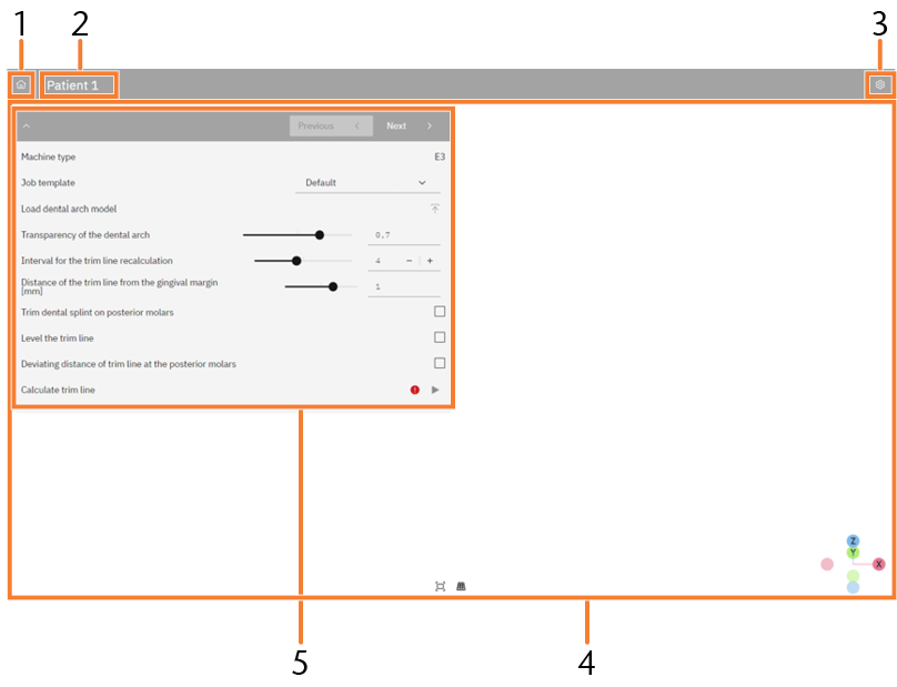
Job view of trimcam
-
Button
-
Job name
-
Information area
-
Button Settings
-
3D display
-
Editing area
Step 2: Importing dental arch models
You import the dental arch model as an STL file. You can import single dental arch models or multiple dental arch models for serial machining. In serial machining, you only use files from the same jaw and the same patient.
trimcam can import trim lines from CAD applications to the PTS and ASC file formats.
-
Make sure that the STL files meet the trimcam requirements.
-
Select
 in the editing area, under Manage dental arch models.
 -
Navigate to the required file(s) in the file browser and select it or them.
-
(Optional) Select all desired trim line files. Make sure that the trim line file(s) meet(s) the following requirements:
-
The first and last points of the trim line must be the same (closed curve).
-
The following must be identical for the trim line file and the associated STL file:
-
File name
-
Folder
-
Coordinate system
-
-
-
Select Open.
-
The dental arch model is displayed in the 3D display.
-
(Optional) trimcam loads the trim line files. The Calculate trim line process is no longer necessary.
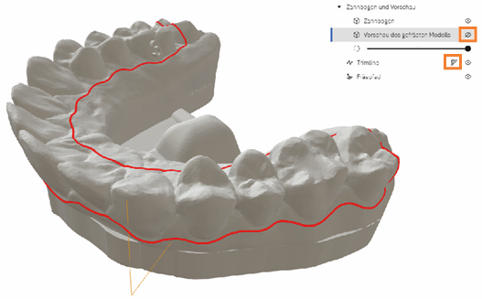
3D display
Depending on the machining step, here the dental arch with or without a base, trim line and milling path are visible. You can adjust the 3D display to your needs.
-
If you are editing multiple dental arch models, select the dental arch model in the editing area that is shown in the 3D display.
-
To show or hide certain elements (dental arch, preview of the milled model, trim line and milling path), select
 .
. -
Use the slider to adjust the transparency of the dental arch model.
-
To adjust the trim line manually, select
 .
. -
Rotate the dental arch model by holding down the left mouse button or using the mouse wheel (depending on the setting).
-
Press and hold the right mouse button to move the dental arch model.
-
Zoom in or zoom out the dental arch model by scrolling the mouse wheel.
-
To center the dental arch model, select
 .
. -
To switch between isometric and perspective view, select
 .
.
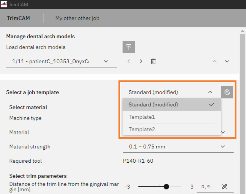
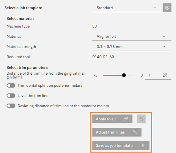
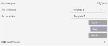
Step 3: Using the job template
The trim, base and material parameters are stored in job templates. The default template is selected in new jobs.
-
To use a different job template, select the template in the selection list.
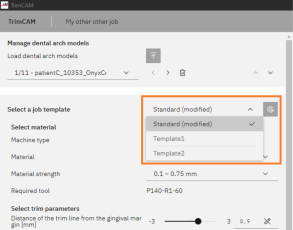
More information on job templates:
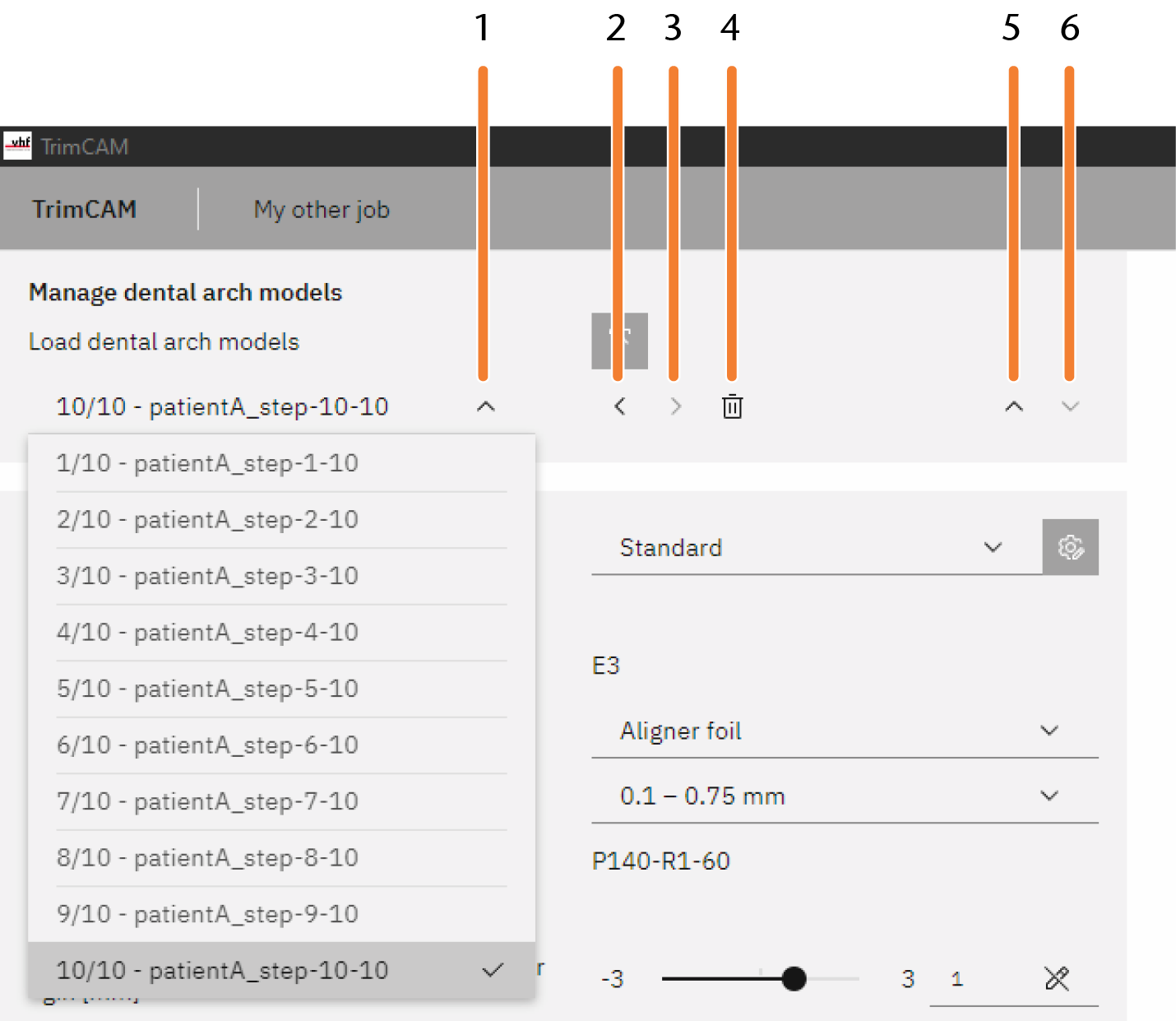
Step 4: Serial machining
trimcam enables series machining for several dental arch models, each representing individual treatment steps for a single patient.
-
In the Manage dental arch models area, load all associated dental arch models into the job.
-
Use the control elements to select, move and delete loaded models.
-
-
Expand and collapse list of dental arch models
-
Select previous dental arch model
-
Select next dental arch model
-
Delete current dental arch model
-
Move current dental arch model up in the list
-
Move current dental arch model down in the list
-
Specify the desired parameters for the individual dental arch models individually.
-
To apply the parameters of the current dental arch model to the entire job, select . If necessary, enable the function by selecting the lock next to the button.
-
To adjust several trim lines automatically by interpolation, select .
-
To save the parameters of the current dental arch model as a template, select Save as job template.
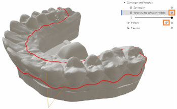
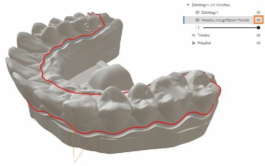
Step 5: Define machining parameters of the job
trimcam starts the calculation of the job and automatically recognizes the trim line as soon as you have imported the first dental arch model. Please note the following:
-
When you change a parameter, the calculation is updated automatically.
You can set all parameters using a slider or a selection list. You cannot enter numerical values directly.
-
You can recognize the status of the selected dental arch model by the progress bar in the editing area.
-
You can switch between the dental arch models of a job to check the status.
-
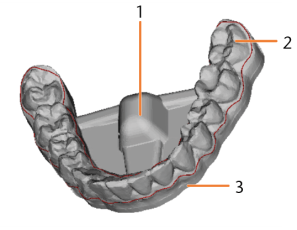
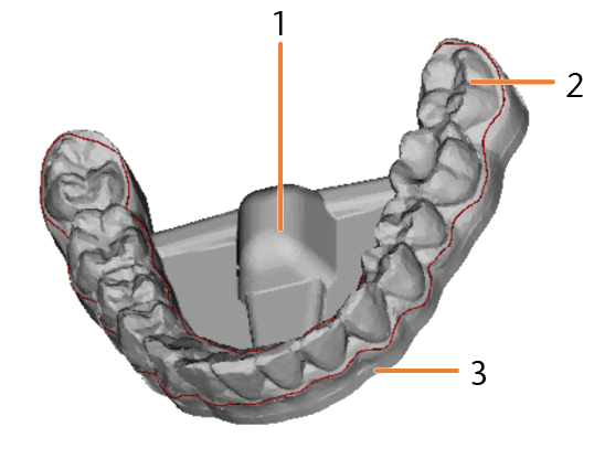
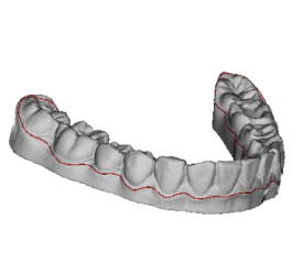
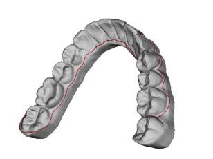
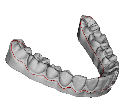
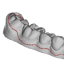
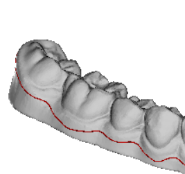
Once a dental arch model has been fully calculated, it is displayed with the base and machine mount in the 3D display. The trim line is shown as a red line.
-
Machine mount
-
Dental arch model
-
Base
-
Selecting material
-
Select an entry from the Material selection list.
-
Select an entry from the Material strength selection list.
-
The required tool is displayed depending on the selected material.
Selecting trim parameters
-
Specify the Distance of the trim line from the gingival margin [mm] parameter.
-
To trim the dental splint at the posterior molars, activate the option Trim dental splint on posterior molars.
-
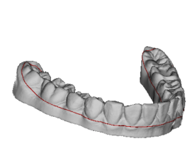
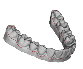
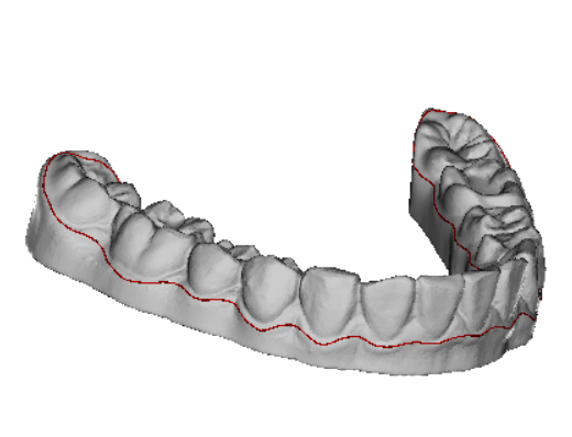
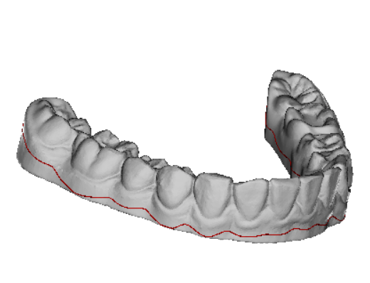
Specify the Trim [%] parameter.
Rule: The higher the value, the stronger the trim on the dental splint at the posterior molars.
Example: Trim of 0%

Example: Trim of 100%
-
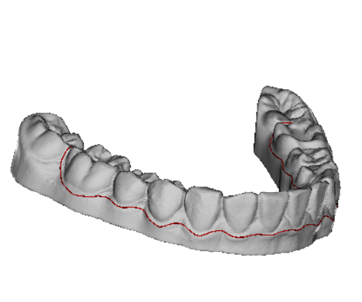
(Optional) To define a different trim at the right and left, activate the option Asymmetric trim.
The information at the right and left refer to the standard top view of the dental arch. You activate the top view by clicking Z .
Example: Trim left of 0%, right of 100%
-
-
To flatten the trim line, activate the option Level the trim line.
-
Specify the Leveling factor parameter.
Rule: The higher the value, the flatter the trim line. The lower the value, the more the trim line follows the curve of the gingival margin.

Example: Leveling factor of 0
Example: Leveling factor of 1.7
-
(Optional) To define a deviating leveling factor on the oral dental surfaces, activate the option Deviating leveling factor oral. Specify the Leveling factor oral parameter.
Example: Leveling factor (global) of 0, deviating leveling factor oral of 1.7
-
(Optional) To level the trim line only from the direction of the interdental spaces (and not from the direction of the gums), activate the option Level the trim line only from the direction of the interdental spaces.
-
To define a deviating distance of the trim line from the gingival margin for the posterior molars, activate the option Deviating distance of trim line at the posterior molars. Specify the parameter.
Rule: The lower the value, the closer the trim line is to the molars.
-
Adjust the parameters described above step by step until you are satisfied with the displayed trim line. Wait for the complete calculation of the dental arch model.
-
If the defined parameters apply to many of your typical jobs, select Save as job template.
-
If necessary, edit the trim line manually using the Trim line editor.
(Optional) Manually edit trim line
Important: As soon as you change additional machining parameters of the job, the calculation of the affected dental arch models is updated and previous adjustments to the trim line are reset.
Example: Distance of 0.5 mm
Example: Distance of 3 mm


Example: Distance (global) of 2 mm, deviating distance of 0.5 mm
Example: Distance (global) of 2 mm, deviating distance deactivated
Selecting further settings
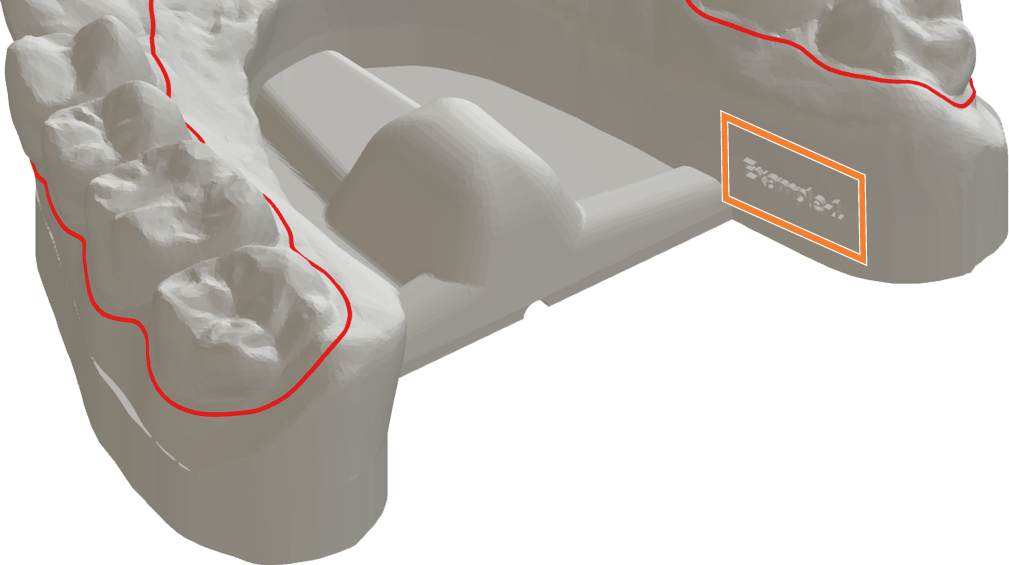
Label dental arch model with file name
You can use this option to activate the labeling of the dental arch model based on the file name. The maximum length of the label is 16 characters.
trimcam automatically calculates a suitable position for the label. The text is shown in the 3D display.
-
Activate the Label dental arch model with file name option.
-
For a recessed label, activate the option Recessed label. Otherwise the label will be raised.
-
Specify the font size for the label.
-
If required, specify an additional text:
-
Enter the text in the text field and select the position before or after the file name.
-
Check the preview and adjust the text if necessary.
-
To accept the text displayed in the preview, select this icon
 .
. -
The additional text is adopted for all dental arch models.
-
Print dental arch model as hollow body
This option allows you to prepare the dental arch model for 3D printing as a hollow body, with or without a support structure. This allows you to save on material costs and speed up machining in your 3D printing software.
No hollow body can be created if the imported model is already a hollow body or is labeled on the underside.
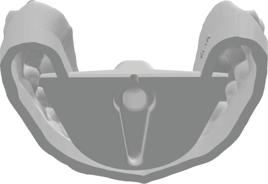
Hollow body model without support structure
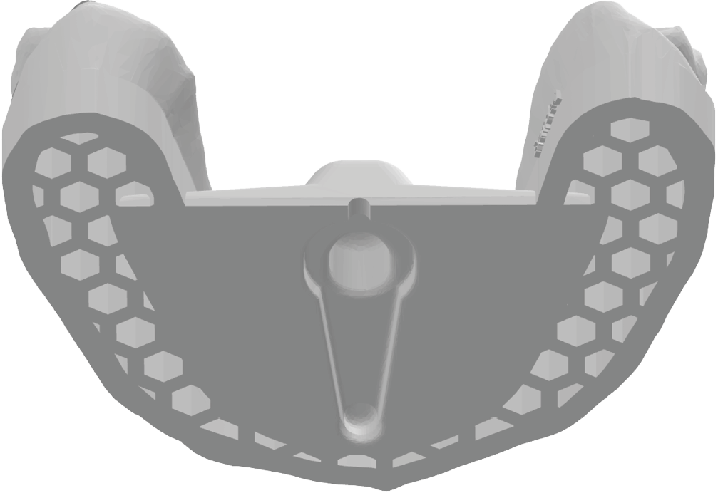
Hollow body model with support structure
-
Activate the Print dental arch model as hollow body option.
-
Determine the thickness of the outer wall with the parameter Wall thickness [mm].
-
To add a honeycomb support structure, activate the Adjust support structure option.
If required, specify the edge length, spacing and depth of the honeycombs.
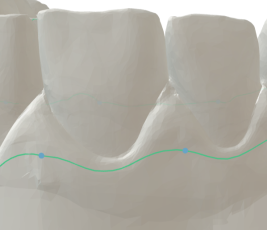
Step 6: (Optional) Manually edit trim line
-
Define all machining parameters for the job and wait until the calculation of the selected dental arch model has been completed.
Important: As soon as you change additional machining parameters of the job, the calculation of the affected dental arch models is updated and previous adjustments to the trim line are reset.
-
Hide the preview of the milled model in the 3D display. Otherwise, the Trim line editor will not be available.

-
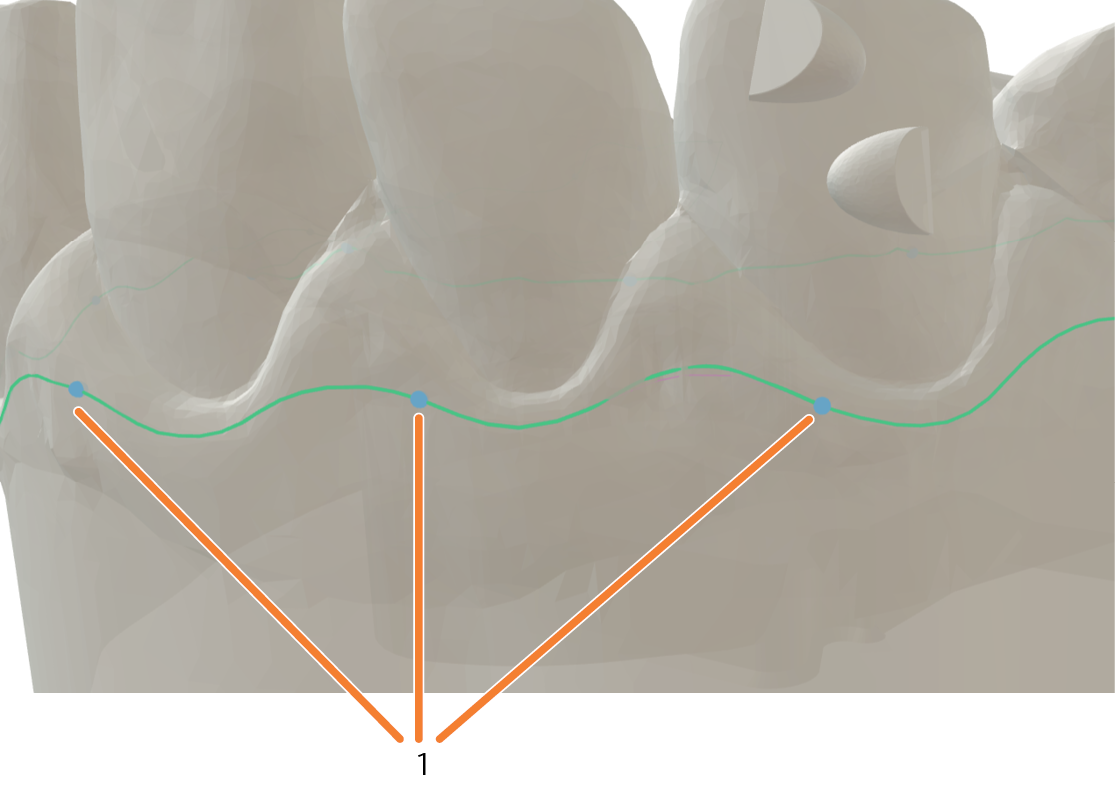
Open the Trim line editor by selecting
in the 3D display. -
The control points functions are displayed.
-
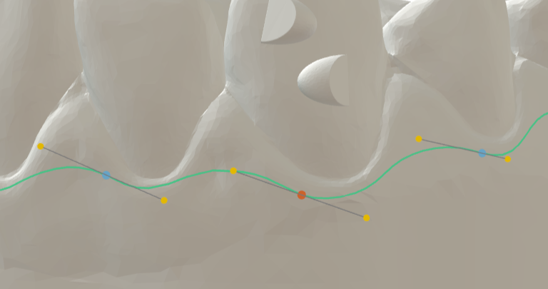
Control points
-
Specify the desired distance between the control points.
Example: Distance between the control points of 8

Example: Distance between the control points of 2
The smaller the distance between the control points, the easier it is to handle.
-
You change the trim line using grip lines at the control points. To display the grip lines, select a control point.

-
Edit the trim line with the control points and grip lines:
-
The longer the grip line, the rounder the curve.
-
The alignment of the grip lines determines the gradient of the curve.
-
Use the following buttons:
Control points
Left-click + drag Move a control point.
Ctrl + left click
Set a new control point.
Del
Delete the selected control point.
Shift + drag
Smooth the curve.
Mouse-over + scroll
Scale the grip lines.
Handle lines
Left click
Move the grip lines.
Shift + drag
Scale the grip lines symmetrically.
Ctrl + drag
Move the grip lines without changing the pitch.
-
-
If necessary:
-
Undo the last change by selecting
 .
. -
Reset the Trim line editor by selecting
 .
.
-
-
If you are satisfied with the result, select Apply.
-
If you want to discard your changes, select


Step 7: (Optional) Managing job templates
-
Set all parameters for a dental arch model as desired.
-
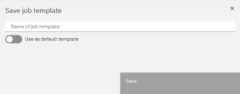
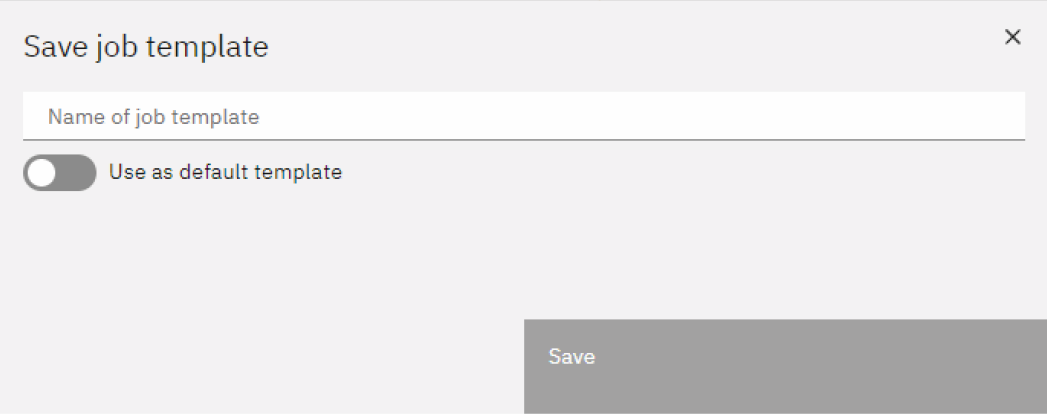
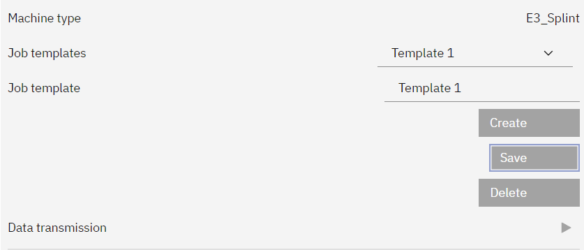
Select Save as job template.
-
A dialog window opens.
-
Give the job template a name via the input field Name of job template.
-
Specify whether you want to use the job template as the default.
You can also subsequently change the default template for new jobs in the settings of trimcam .
-
Select Save.
-
To manage job templates, select the
 icon next to the list of job templates.
-
trimcam opens the window in which you manage the job templates.
-
Import job template
-
Display and select job templates
-
Delete selected job template
-
Export selected job template
-
Rename the selected job template with the content of the text field
-
-
Once you have made the desired changes, select .
Step 8: (Optional) Transfer job to another computer
You can export jobs to trimcam and import them to another computer with trimcam .
-
To export the currently open job, select the
 icon in the information area.
trimcam opens a window to save the job as a MADF file.
-
Enter the desired file save location.
-
Transfer the file to the desired computer.
-
On the trimcam start page, select Import.
Step 9: Transfer data to dentalcnc
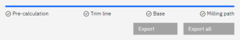
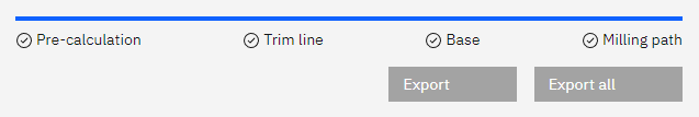
Once you have completely adjusted a dental arch model and the calculation is finished, you can export the model.
-
To export the selected dental arch model, select Export.
-
To export all dental arch models of the job, select Export all.
-
The following happens:
-
The dental arch models are displayed in the job list of dentalcnc.
-
The STL file for the 3D printout is saved in the corresponding output directory.
What's next?
-
If you want to machine the job right away, switch to dentalcnc and start machining.
-
If you want to create additional jobs, select
 .
. -
If the calculated job is not displayed in dentalcnc, select Settings and check if the correct output folder was selected.