Applies to: Dental machines
Milling zirconia
How to mill zirconia? Are there nesting guidelines for zirconia discs?
Introduction
If you want to achieve perfect results, you should pay attention to the following points:
- The collet chuck of the spindle needs to be tightened firmly, otherwise the tool will be pressed into the collet chuck.
- The collet chuck of the spindle needs to be clean and without grease inside, otherwise rotational imperfections during machining will degrade the machining results and can cause tool breakages.
- The .stl-file must be free from design errors .
Furthermore, there are a few things you can do if you would prefer to be on the safe side:
- Activate the option in DentalCAM.
- Add at least 1 backup tool to the tool magazine in case of a tool breakage.
vhf machines suitable for milling zirconia
| Machine | Wet /dry machining | Material | Supported holder |
|---|---|---|---|
|
K4 / K4 edition |
Dry machining |
Only K4 edition: Blocks |
Only K4 edition: Block holder |
|
K5 / K5+ |
Dry machining |
Discs, Blocks |
Block holder |
|
N4 / N4+ |
Wet machining |
Blocks |
|
|
R5 |
Dry machining |
|
Block holder |
|
S1 |
Dry machining |
Discs, Blocks |
Block holder |
|
S2 / S5 |
Dry machining |
Discs, Blocks |
Block holder |
|
Z4 |
Wet machining |
Blocks |
Tools for machining zirconia
| Match code (4-axis except E4) | Match code (5-axis plus E4) | Cutting edge diameter | Tool geometry | Teeth | DentalCAM 7 | DentalCAM 8 |
|---|---|---|---|---|---|---|
|
Z060–R2D–35 |
Z060–R2D–40 |
0.6 mm |
Radius |
2 |
Yes |
Yes |
|
Z100–R2–35 |
Z100–R2–40 |
1.00 mm |
Radius |
2 |
Yes |
Yes |
|
Z100–R2D–35 |
Z100–R2D–40 |
1.00 mm |
Radius |
2 |
Yes |
Yes |
|
Z120–F2D–35 |
Z120–F2D–40 |
1.20 mm |
Flat |
2 |
Yes |
Yes |
|
Z200–R3–35 |
Z200–R3–40 |
2.00 mm |
Radius |
3 |
Yes |
Yes |
|
Z200–R3D–35 |
Z200–R3D–40 |
2.00 mm |
Radius |
3 |
Yes |
Yes |
|
- |
Z200-R3D–40-T |
2.00 mm |
Radius |
3 |
No |
Yes |
We highly recommend the use of original vhf tools for optimal results and a high service life of your machine and its components.
Correct setting of bars
Positioning bars in X- and Y-direction
| Correct | Incorrect | Description |
|---|---|---|
|
|
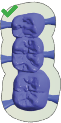
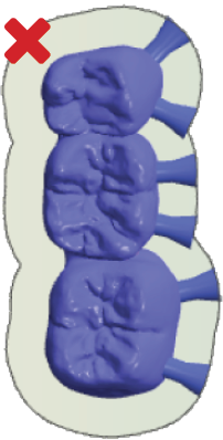
Place bars evenly on all sides If you place bars on only one side, vibration during machining may occur. This can lead to the blank or tool getting damaged. Correct (left): Bars on all sides of the object Incorrect (right): Bars on only one side of the object |
|
|
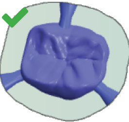
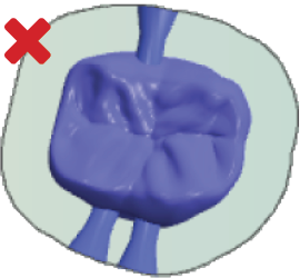
Place bars with sufficient distance from each other If there isn't enough space between bars, the air nozzle of the spindle may not be able to blow off machining debris as required, which can damage the tool. Correct (left): Bars with suitable distances between them Incorrect (right): Bars without suitable distances between them |
|
|
|
Set enough bars You should at least set 3 bars for each object. Multi-unit-objects generally require 2 bars per unit. Otherwise, vibrations may occur during machining, which can lead to the blank or tool getting damaged. Correct (left): Enough bars have been set Incorrect (right): Too few bars have been set |
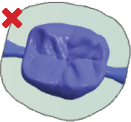
Positioning bars in Z-direction
- Position all bars on the equator. If the equator is on the prepline, position the bar approx. 1 mm above the equator.
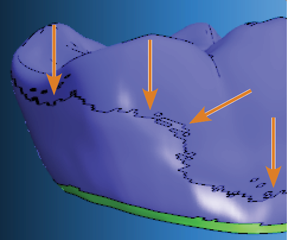
Equator marked with arrows
Equator marked with arrows
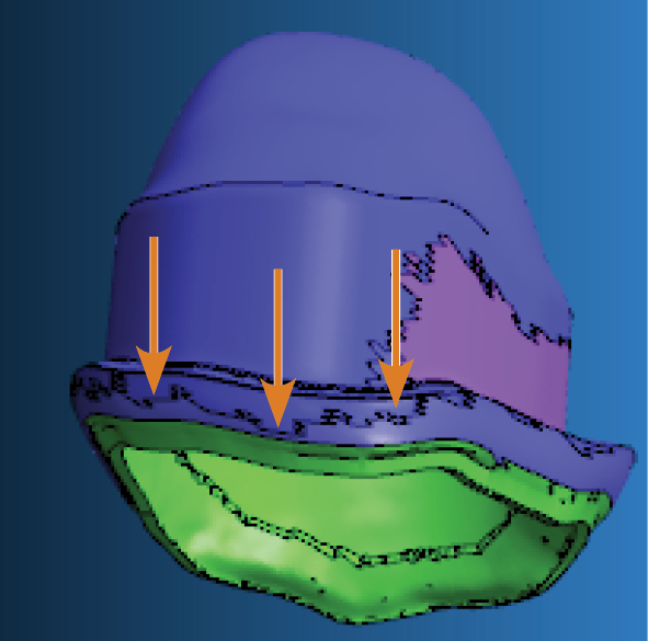
You need to position all bars completely on the object.
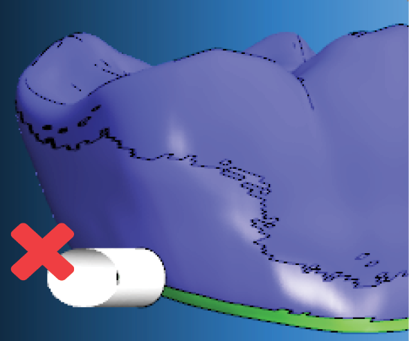
The bar in the figure below is positioned too high. Only a part of the bar is positioned on the object.
Incorrect positioning of a bar
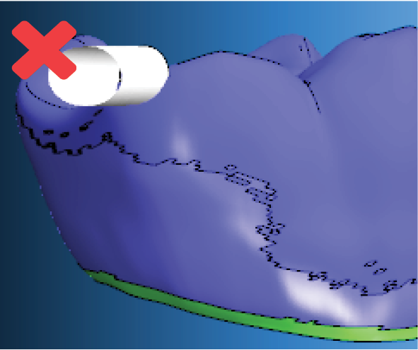
The bar in the figure below is positioned too low. Only a part of the bar is positioned on the object. Additionally, the bar is positioned on the prepline.
Incorrect positioning of a bar
The bar in the figure below is correctly positioned on the equator.
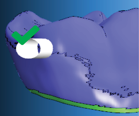
Correct positioning of a bar
Special recommendations for nesting objects in translucent zirconia discs
Translucent zirconia discs can be very sensitive and are easily damaged or scratched. Therefore, we recommend that you follow the general steps below when nesting objects in translucent zirconia discs.
- If possible, nest objects from the center to the disc border.
- If you activate the Deactivate safety distance to the blank border option in the DentalCAM settings, only mount the discs directly into the blank holder. Do not use the blank changer
 Machine component which stores multiple blanks in a magazine and which can automatically load them into the working chamber.. When using the search, use a blank changer or a blank magazine instead.
 - If you add objects to a disc and process it multiple times, follow the guidelines for different object sizes below.
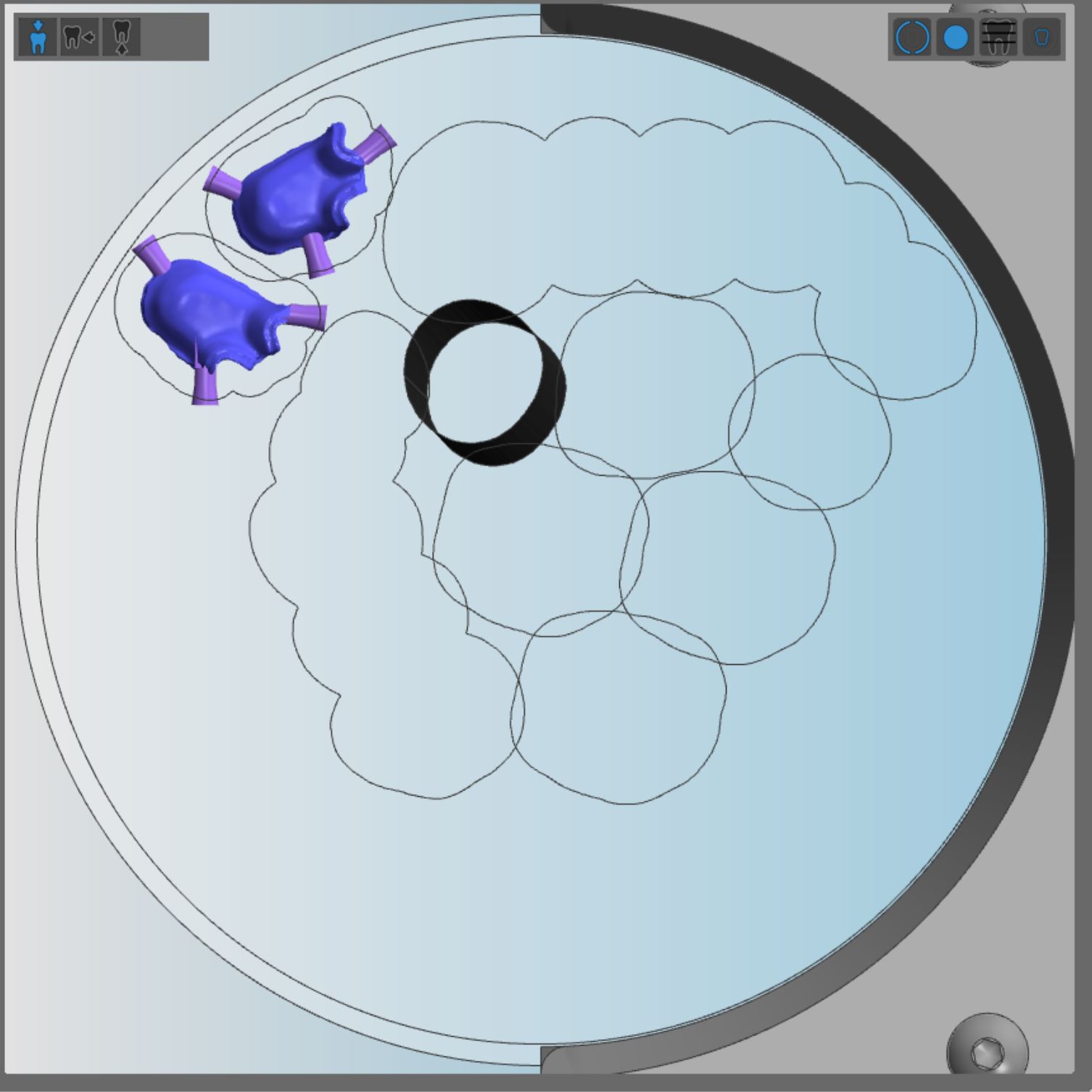
Small and medium sized objects
If you process a disc multiple times, we recommend that you nest small and medium sized objects in the following way:
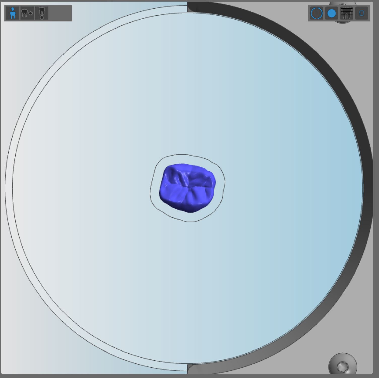
- Position a small, round object in the disc center.
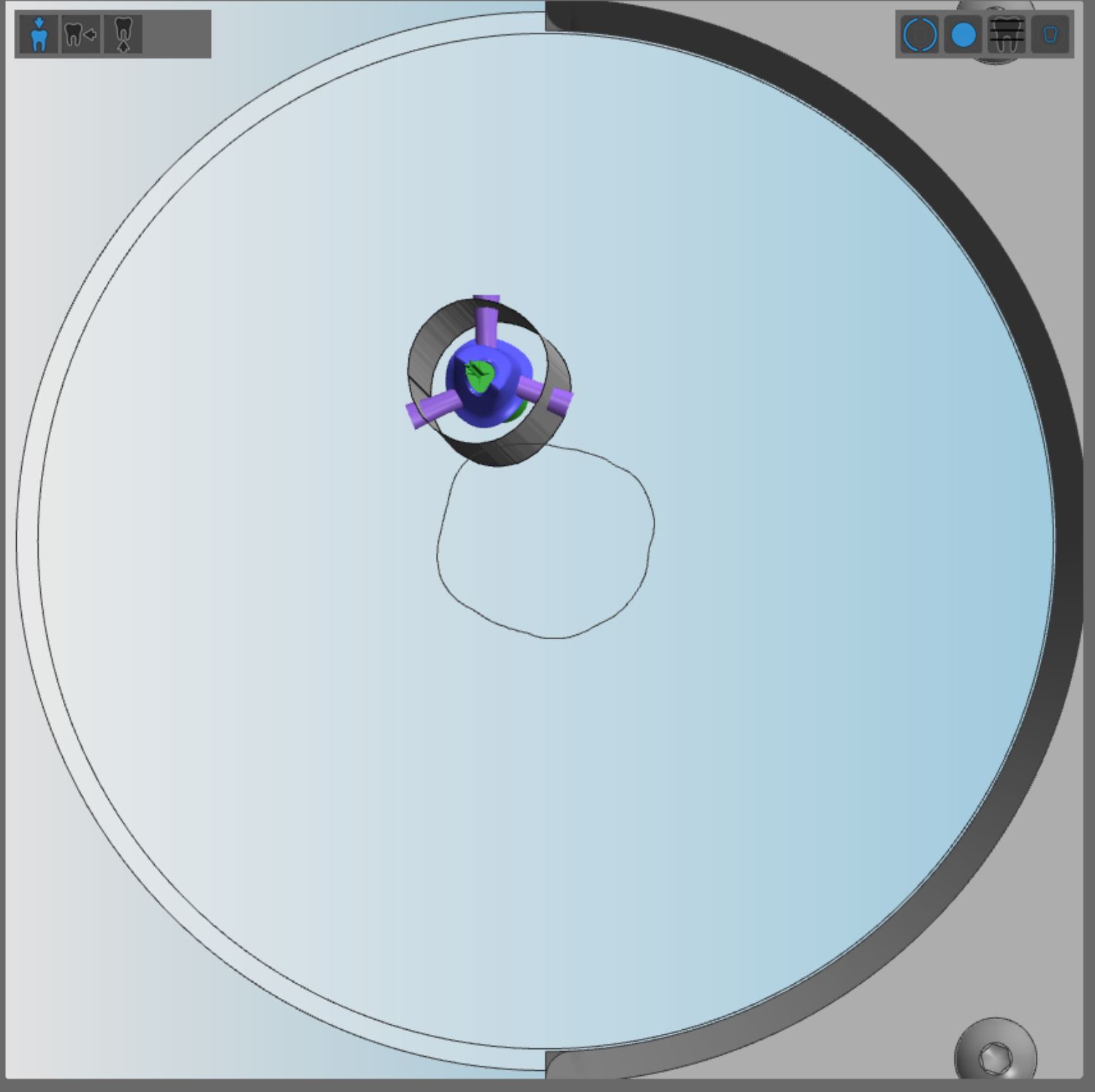
- Position the next objects circularly around the first object.
- Continue to nest objects from inside out.
- You have nested objects from the blank center towards the border.
Example:
Step 1
Step 2
Step 3
Step 4
Step 5
Step 6
Step 7
Step 8
Step 9
Step 10
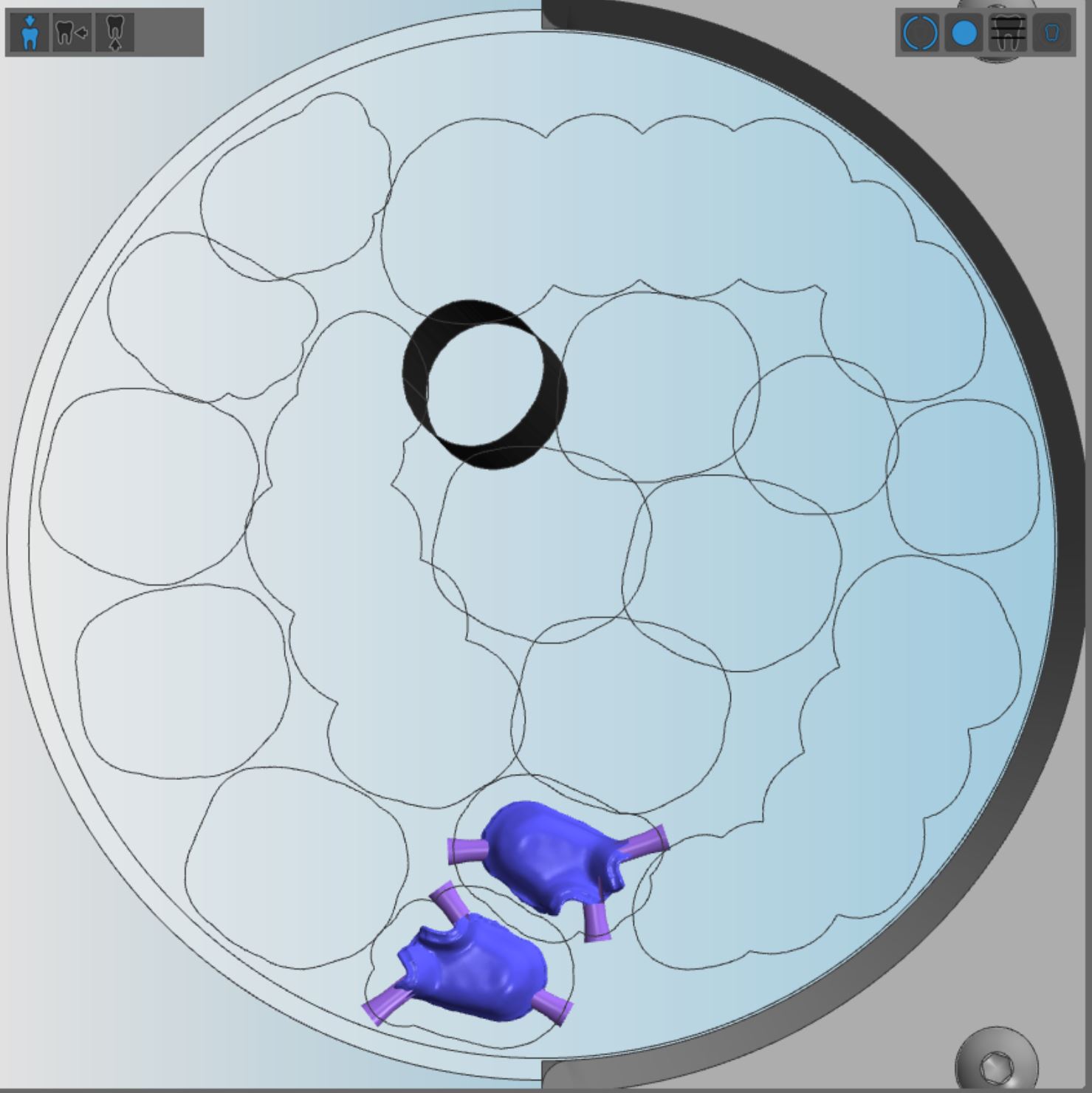
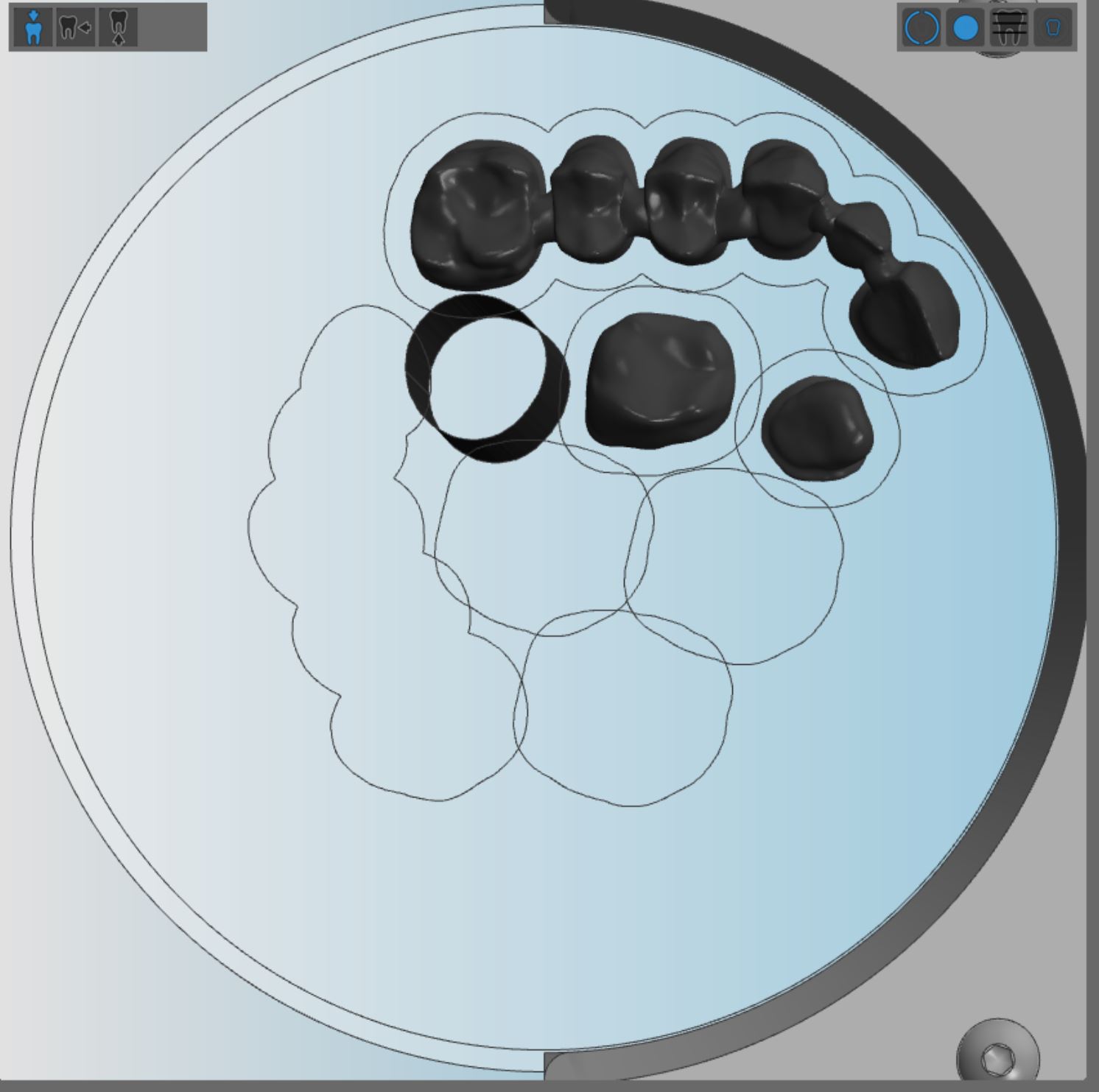
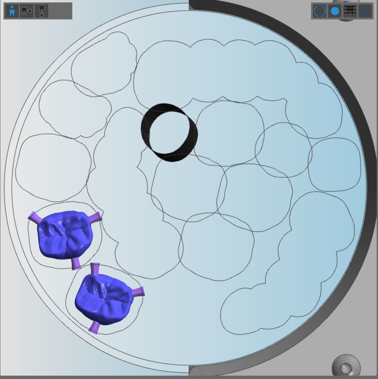
Medium sized objects
If you process a disc multiple times, we recommend that you nest medium sized objects in the following way:
- Position the first object in the disc center.
- Position the next object adjacent to the first object.
- Continue to nest objects from inside out.
- You have nested objects from the blank center towards the border.
Example:
1
2
3
4
5
6
7
8
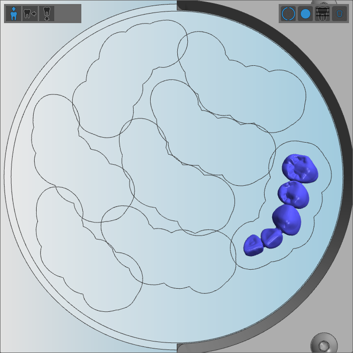
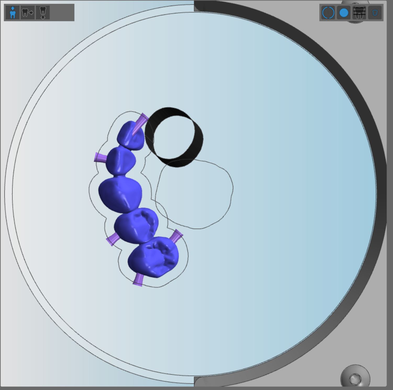
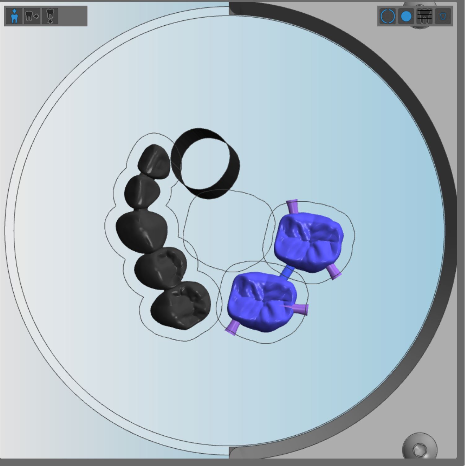
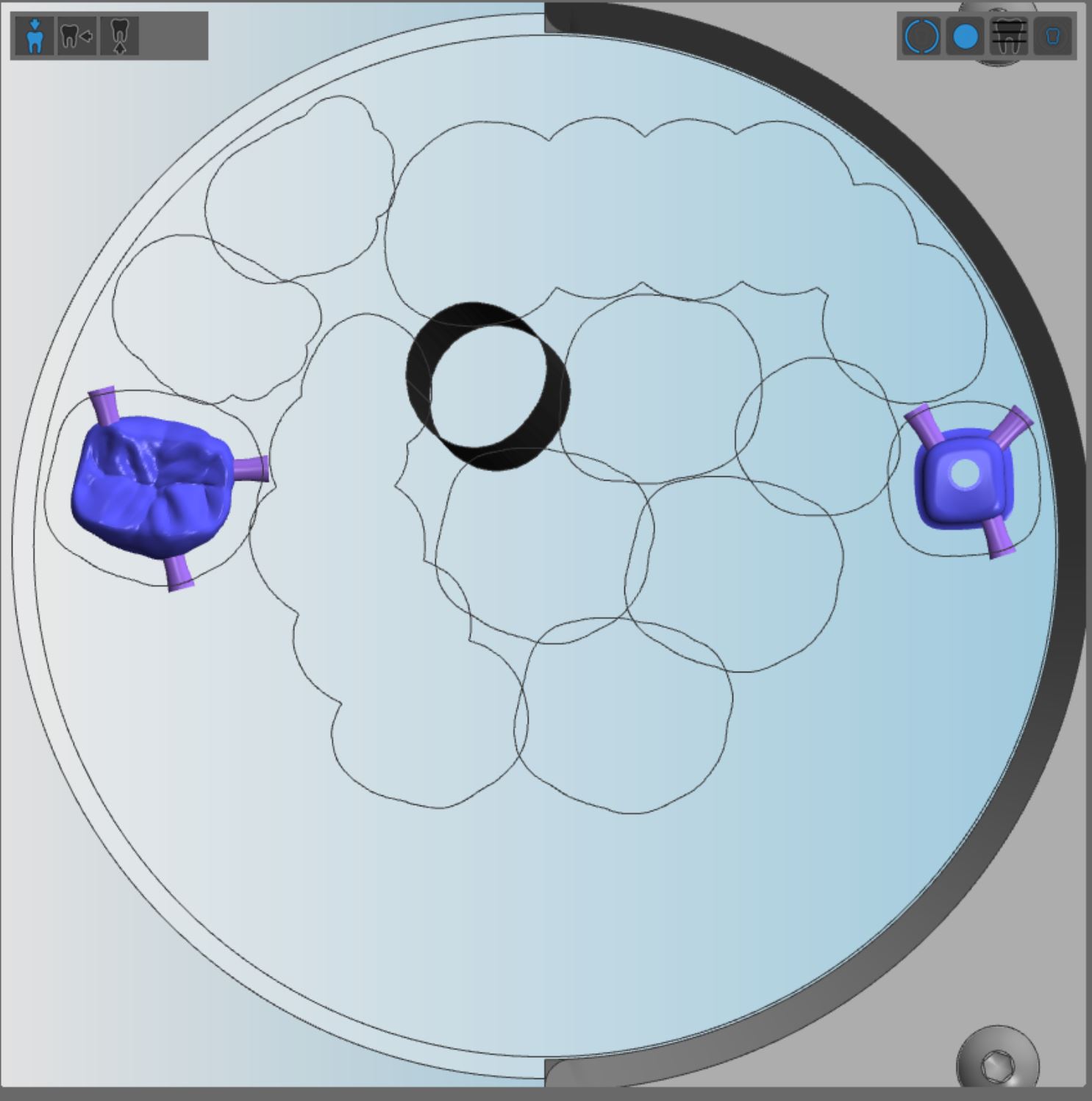
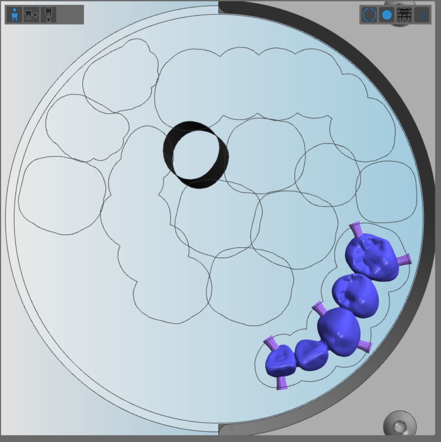
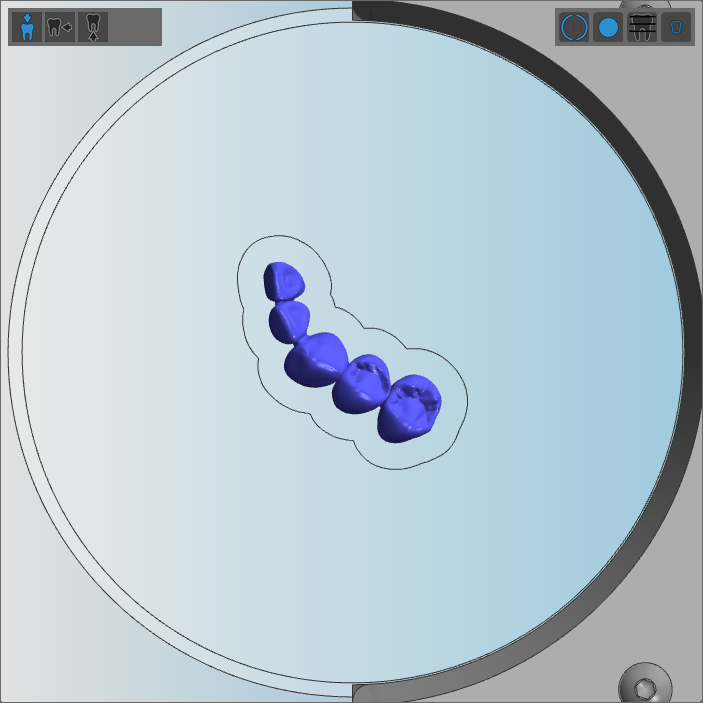
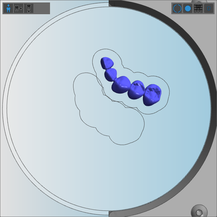
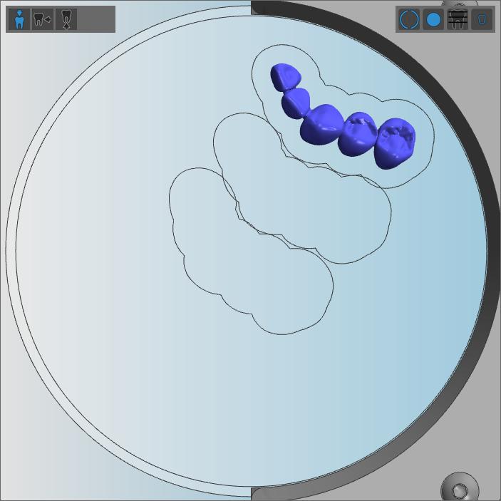
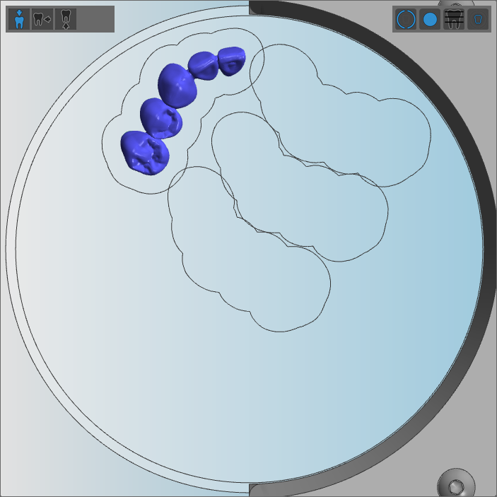
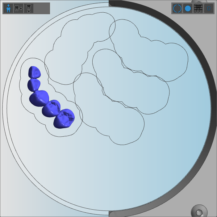
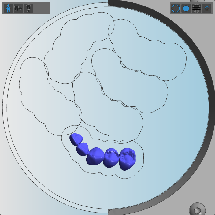
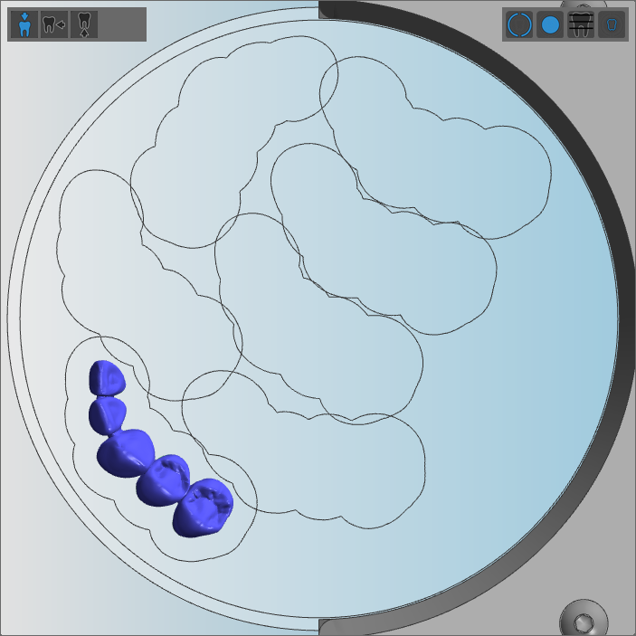
Multiunit bridge with a sinter bar and several small objects
If you process the disc multiple times, we recommend that nest said objects in the following way:
- Position the multi-unit bridge on the left side of the disc. Otherwise, you would not be able to reuse the disc because its stability would be too low after removing the bridge.
- Execute the job.
- Position the smaller objects in the remaining area.
Example:
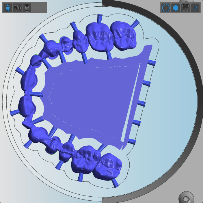
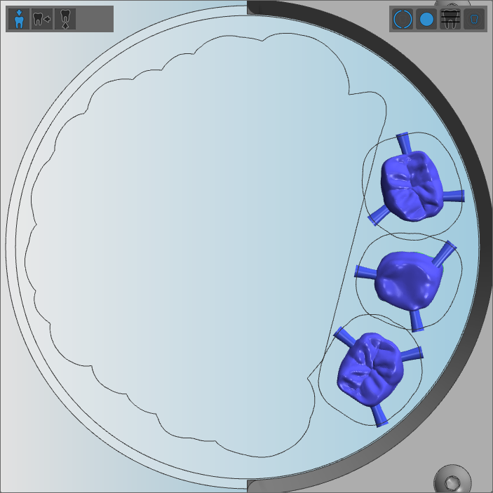
(a) Step 1 – positioning the multiunit bridge; (b) Step 2 – positioning the smaller objects