Nesting rules for connectors

Connectors that were incorrectly set are one of the most frequent causes for bad machining results. The rules and recommendations in this help article will help avoid common mistakes.
Use a sufficient number of connectors
|
|
Discs |
Blocks |
|---|---|---|
|
Single-part objects/Small objects |
3 |
1 |
|
Multi-unit objects
|
1–2 on the outer units 1 per inner unit For a sinter bar: 1 connector every 20 mm from sinter bar to material |
3 |
Using the correct bar types and bar parameters
- In particular, for multi-unit objects, sufficient partially reduced or intact connectors must remain after manufacturing to prevent the object from falling. Arrange these connectors so that the object is securely fastened at all points after manufacturing.
-
For objects with only 1 connector, select a larger node diameter.
Position the connectors correctly
General guidelines for minimizing rework:
-
Place the connectors outside of fissures.
-
If possible, avoid positioning connectors on the labial side. If necessary to ensure stability, place the connectors in the interdental spaces, provided there is enough space.
-
For relevant objects, place the connectors in areas that will be covered by veneers whenever possible.
Positioning connectors in X- and Y-direction
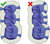
Place bars evenly on all sides
If you place bars on only one side, vibration during machining may occur. This can lead to the blank or tool getting damaged.
(): Bars on all sides of the object
Incorrect (right): Bars on only one side of the object
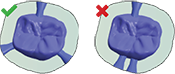
Place bars with sufficient distance from each other
If there isn't enough space between bars, the air nozzle of the spindle may not be able to blow off machining debris as required, which can damage the tool.
(): Bars with suitable distances between them
Incorrect (right): Bars without suitable distances between them
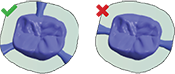
Set enough bars
You should at least set 3 bars for each object. Multi-unit-objects generally require 2 bars per unit. Otherwise, vibrations may occur during machining, which can lead to the blank or tool getting damaged.
(): Enough bars have been set
Incorrect (right): Too few bars have been set
Positioning connectors in Z-direction
- Position all bars on the equator. If the equator is on the prepline, position the bar approx. 1 mm above the equator.
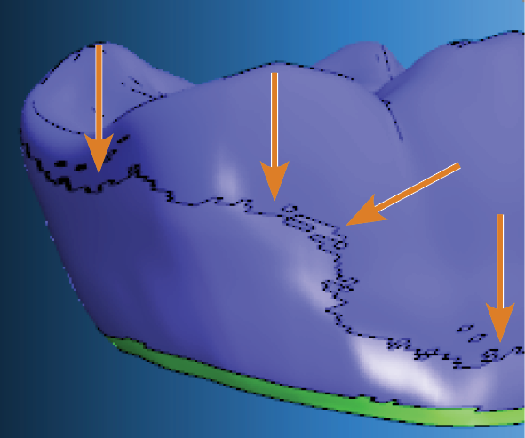
Equator marked with arrows
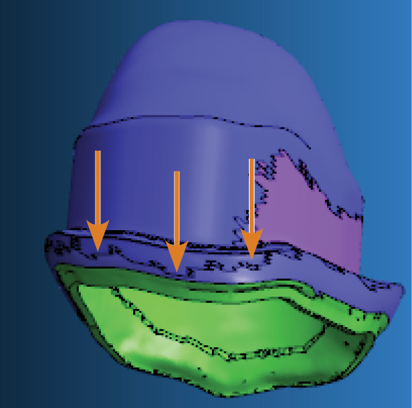
Equator marked with arrows
You need to position all bars completely on the object.
The bar in the figure below is positioned too high. Only a part of the bar is positioned on the object.
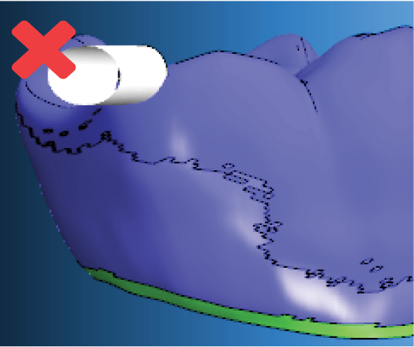
Incorrect positioning of a bar
The bar in the figure below is positioned too low. Only a part of the bar is positioned on the object. Additionally, the bar is positioned on the prepline.
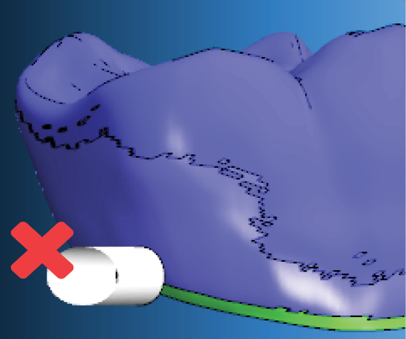
Incorrect positioning of a bar
The bar in the figure below is correctly positioned on the equator.
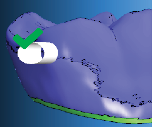
Correct positioning of a bar
Positioning connectors on surfaces with sufficient material thickness
Always position connectors on convex surfaces with sufficient material thickness. Otherwise, the stability of the connectors may become too low and you will have to rework the object manually.
The following figure shows an inlay where the material thickness on the left side is not high enough to position a stable connector. The right side is suitable.
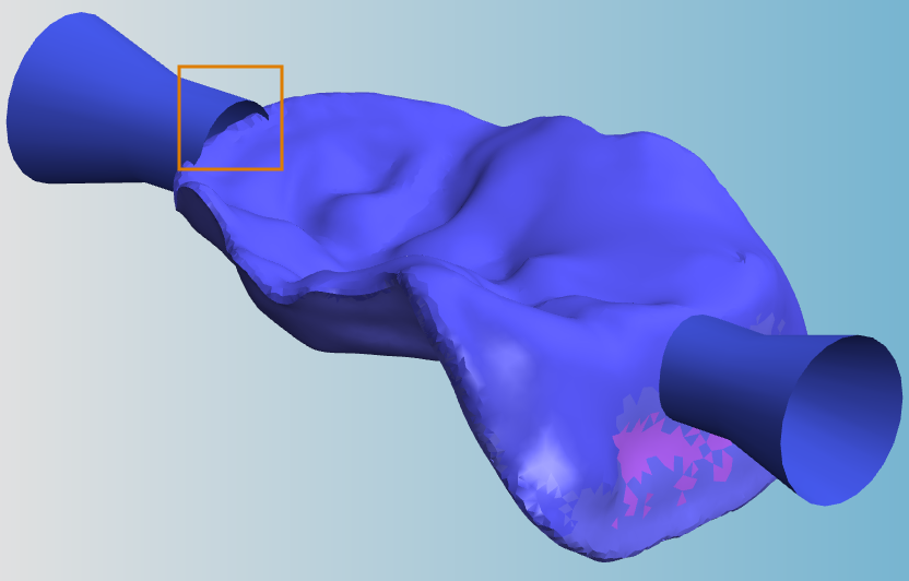
An inlay with 2 bars: The left bar is misplaced
Customize objects in blocks
For blocks, the standard orientation of the objects may be unsuitable for the connector that runs from the object to the shaft of the block.
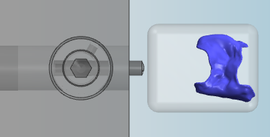
Original orientation of an inlay in a block (top view)
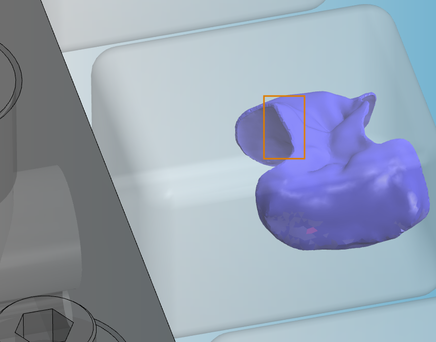
Original orientation of an inlay in a block (3D view)
In this case, you need to rotate the object about the Z-axis so that you can position the connector on a surface with sufficient material thickness.
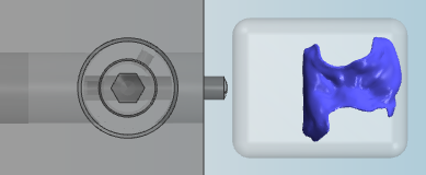
After rotating the inlay, you can place a bar on the appropriate side (top view)
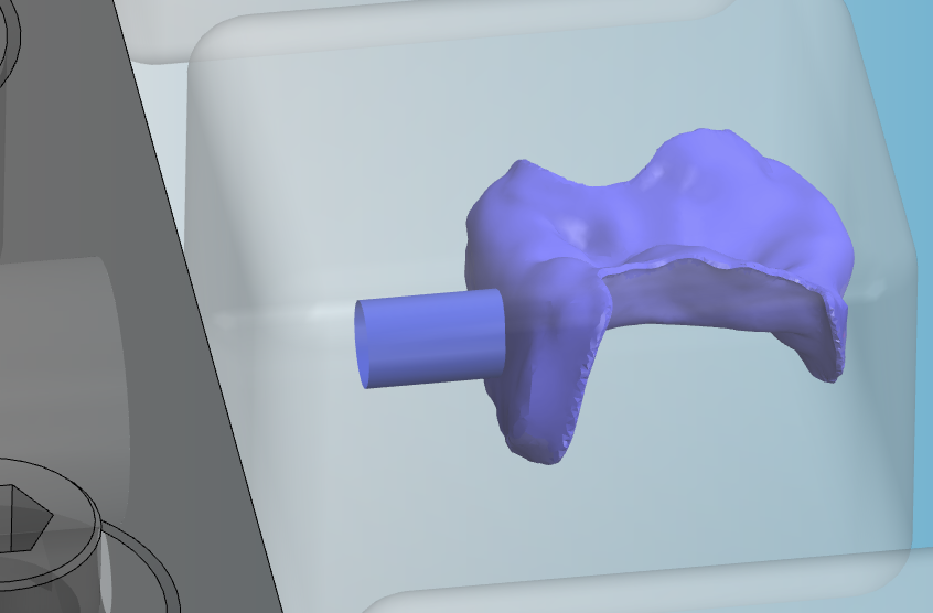
After rotating the inlay, you can place a bar on the appropriate side (3D view)
Using convex surfaces and avoid concave surfaces
Always position connectors on convex surfaces because these surfaces can adequately support connectors. The stability of connectors positioned on concave surfaces may be insufficient.
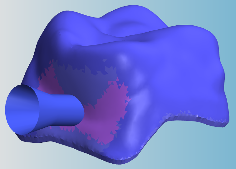
Connector on a concave surface (incorrect)
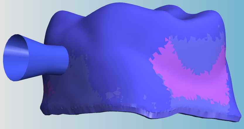
Connector on a convex surface (correct)


